
Omron D7A-2


- Part Number:
D7A-2
- Manufacturer:
- Category:
- RoHs:
 RoHS Compliant
 - Datasheet:
 D7A-2_Datesheet
 - Description:
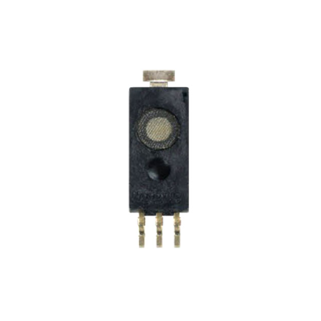
SENSOR VIBRATION HORZ 90-170GAL
- In stock 0

D7A-2 Horizontal Vibration Detection Switch – Complete Technical Specifications
1. Product Identification
Product Name: Automatically Small Horizontal Vibration Detection Switch
Type Name:D7A-2
Document Number: No. 1778281-3A1
Issue Date: April 22, 1999
Manufacturer: OMRON Corporation
Drawing Number: DRWG. No. 6421443-2
2. Mechanical Structure & Operating Principle
2.1 Basic Mechanism
- Structure Type: Mechanical contact system that opens/closes via earthquake wave vibration
- Protection Rating: IP40 (protected against solid objects >1mm, no liquid protection)
- Return Mechanism: Automatic return type (self-resetting)
2.2 Sensitivity Specifications
- Set Sensitivity Range: 90–170 cm/s² (Gal)
- Test Method: Horizontal continuous excitation at 0.3, 0.5, and 0.7 cycle/second frequencies
- Operating Threshold: Designed to activate at earthquake wave intensities of 80–250 cm/s²
2.3 Response Times
- Horizontal Return Time: ≤ 20 seconds (time to return to normal state after device is fixed at installation level allowance, at 10°C or higher)
- Circuit Return Time: ≤ 1 minute (time for switch circuit to return to original state after vibration stops)
2.4 Installation Requirements
- Mounting Method: PCB mounting (board thickness: 1.6 mm)
- Installation Level Allowance: ±5 degrees or less from horizontal when installed normally
- Contact Operation: Excites horizontally and turns ON when vibration exceeds set sensitivity threshold
3. Electrical Specifications
3.1 Electrical Ratings
- Voltage: DC 3V
- Current Range: 5 mA to 1 mA (Note: The document shows "DC3V, 5A~DC3V, 1mA" but this appears to be a typo likely meaning 5mA to 1mA based on typical relay/contact specs)
3.2 Electrical Performance
- Contact Resistance: ≤ 1 Ω (initial value)
- Insulation Resistance: ≥ 100 MΩ (measured with DC 250V Megger)Tested between each terminal and earth terminalTested between same-pole terminals
- Dielectric Strength: AC 250V, 50/60 Hz for 1 minuteTested between each terminal and earth terminalTested between same-pole terminals
4. Environmental Operating Conditions
4.1 Operating Environment
- Temperature Range: -10°C to +70°CConditions: No dew formation or freezing permitted
- Humidity Range: 25% to 95% RH
4.2 Storage Environment
- Temperature Range: -30°C to +70°CConditions: No dew formation or freezing permitted
- Humidity Range: 25% to 95% RH
5. Mechanical Durability & Environmental Resistance
5.1 Transportation & Handling Tests
| Test Type | Conditions | Requirements |
|---|---|---|
| Transportation Vibration | Half amplitude: 2.5mm, Frequency: 10Hz, Duration: 20+ minutes, 3 axes | Satisfy initial values |
| Endurance Impact | Acceleration: 980 m/s², 3 axes, 3 continuous times | No functional obstacle |
| Transportation Impact | Drop height: 60cm to concrete, 3 surfaces/edges, 7 total drops (packed) | Satisfy initial values |
| Terminal Strength | Compression load: 9.8N for 1 minute | Satisfy initial values |
5.2 Environmental Endurance Tests
| Test Type | Conditions | Performance Criteria |
|---|---|---|
| Salt-Fog Test | JIS Z 2371 standard, 100 hours | - No rust/corrosion on external surfaces - Insulation resistance ≥ 5 MΩ - Dielectric strength: AC 250V 1 minute |
| Wet Proofing | 40±2°C, 90-98% RH, 96 hours | - No functional obstacle - Insulation resistance ≥ 10 MΩ |
| Heat-Humidity Cycle | 10 cycles per Figure 2 (24h cycle) | - No functional obstacle - Insulation resistance ≥ 10 MΩ |
| High Temperature Leaving | 96 hours at 70±2°C | No functional obstacle |
| Heatproof Impact | 10 cycles: -30°C (30min) → +70°C (30min) | No functional obstacle |
| Electrical Service Life | 10,000 operations at DC 3V 1mA, 10-20 cycles/min | - No functional obstacle - Insulation resistance ≥ 10 MΩ |
| Corrosive Gas | H₂S: 5±1 ppm, 40°C, 65% RH, 96 hours | Contact resistance ≤ 1 kΩ after test |
6. Soldering Specifications
6.1 Dip Soldering
- Maximum Temperature: 270°C
- Maximum Duration: 4 seconds
6.2 Hand Soldering (Iron)
- Temperature: 350°C ±10°C
- Maximum Duration: 3 seconds
7. Performance Criteria Definitions
7.1 "Satisfy Initial Value" Means:
- Operation Characteristic: Activates at 90–170 cm/s² (0.3, 0.5, and 0.7 cycle seconds)
- Contact Resistance: ≤ 1 Ω
- Insulation Resistance: ≥ 100 MΩ
- Dielectric Strength: Withstands AC 250V, 50/60 Hz for 1 minute
7.2 "No Functional Obstacle" Means:
- Operation Characteristic: Activates at 80–250 cm/s² (0.3, 0.5, and 0.7 cycle seconds)
- Contact Resistance: ≤ 100 Ω
- Insulation Resistance: ≥ 100 MΩ
- Dielectric Strength: Withstands AC 250V, 50/60 Hz for 1 minute
8. Quality Assurance & Warranty
8.1 Guarantee Terms
- Guarantee Period: 1 year after product delivery
- Scope of Guarantee: Exchange or repair of defective parts caused by manufacturer responsibility
- Exclusions: Labor costs and damage compensation not covered
8.2 Specification Validity
- Valid Period: 1 year from issue date
- Revalidation: Specification becomes invalid if no orders received within 1 year
9. Dimensional Specifications
9.1 Key Dimensions (from drawing 6421443-2)
Overall Dimensions:
- Width: 20.0 ± 0.1 mm
- Depth:  2.0 ± 0.1 mm
- Height: 19.6 ± 0.1 mm

Mounting Hole Spacing: 2 ± 0.1 mm (center-to-center)
PCB Mounting: Designed for 1.6mm thick PCB
9.2 Scale & Tolerances
- Scale: 2:1 (as noted on drawing)
- General Tolerance: ±0.4 mm unless otherwise specified
10. Compliance & Standards
- Ingress Protection: IP40 rated
- Environmental Testing: Per JIS (Japanese Industrial Standards)Salt spray: JIS Z 2371Humidity/heat cycles: Per gas meter regulations
- Quality Management: OMRON inspection regulations for microcomputer components
11. Important Notes
- Sensitivity Calibration: Factory-set for 90-170 cm/s² operation; designed to detect earthquake vibrations in the 80-250 cm/s² range
- Installation Critical: Must be mounted within ±5° of level for proper operation
- Temperature Dependency: Return time specifications are valid at 10°C or higher
- Maintenance: No user-serviceable components; automatic return mechanism eliminates need for manual reset
- PCB Design: Ensure 1.6mm PCB thickness for proper mounting and stress relief
12. Manufacturer Information
OMRON Corporation
Corporate Headquarters: Kyoto, Japan
Product Category: Automatic Control Components
Document Control: No. 1778281-3A1 (4-page specification)
Engineering Change History:
- E/C No. A1: Changed to SI units, updated OMRON inspecting regulations for microcomputer (dated 990421)
Purchase
No need to register to order from JMChip Electronics, but signing in lets you track your order like a pro. Give it a try for a smoother shopping ride.
Means
Easy peasy! Pay your way with PayPal, Credit Card, or wire transfer in USD. We've got you covered.
RFQ(Request for Quotations)
Get the freshest prices and stock updates by asking for a quote! Our sales team will shoot you an email within a day. It's that simple.
IMPORTANT NOTICE
1. Look out for your order details in your inbox! (If it's missing, check the spam folder just in case.)
2. Our sales manager will double-check the order and keep you posted on any price or stock changes. No worries, we've got you covered.

Shipping Rate
We ship orders once a day around 5 p.m., except Sunday. Once shipped, the estimated delivery time depends on the courier company you choose, usually 5-7 working days.

Shipping Methods
We provide DHL, FedEx, UPS, EMS, SF Express, and Registered Air Mail international shipping.


Payment
You can pay the orders on the website directly or pay by wire transfer offline. We support: Paypal、VISA、Credit Card.


Omron