
Texas Instruments LMZ21701SILR


- Part Number:
LMZ21701SILR
- Manufacturer:
- Category:
- RoHs:
 Non-RoHS Compliant
 - Datasheet:
- Description:
Non-Isolated PoL Module DC DC Converter 1 Output 0.9 ~ 6V 1A 3V - 17V Input
- In stock 0

LMZ21701SILR Supplementary Information
1. Core Packaging & Ordering Specifications
1.1 Basic Package Attributes
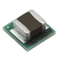
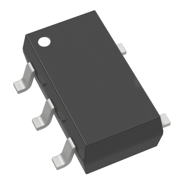
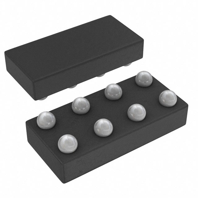
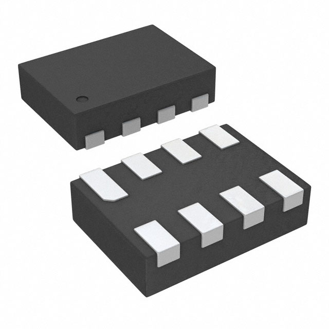
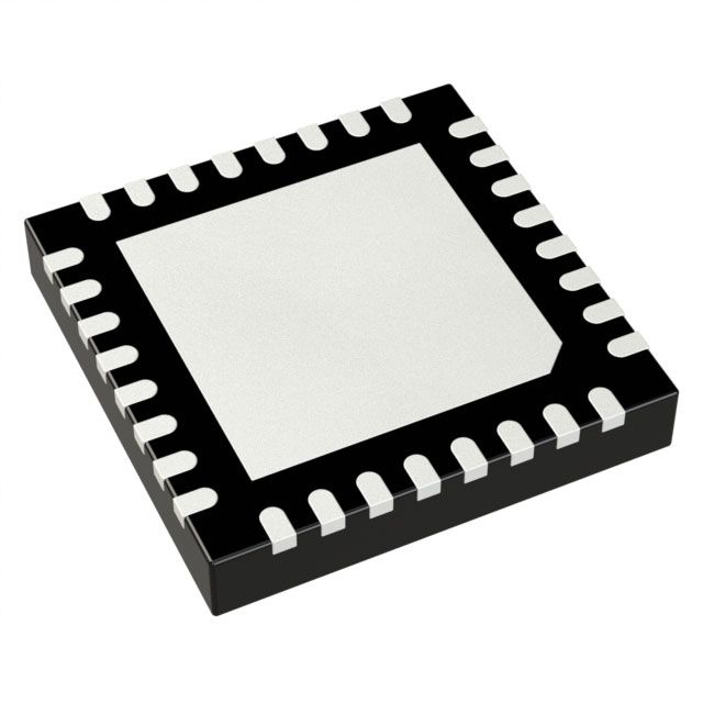
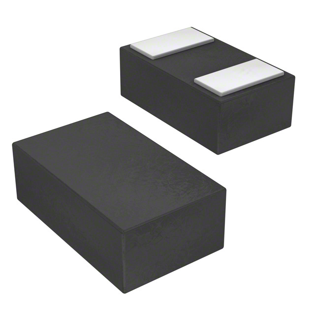
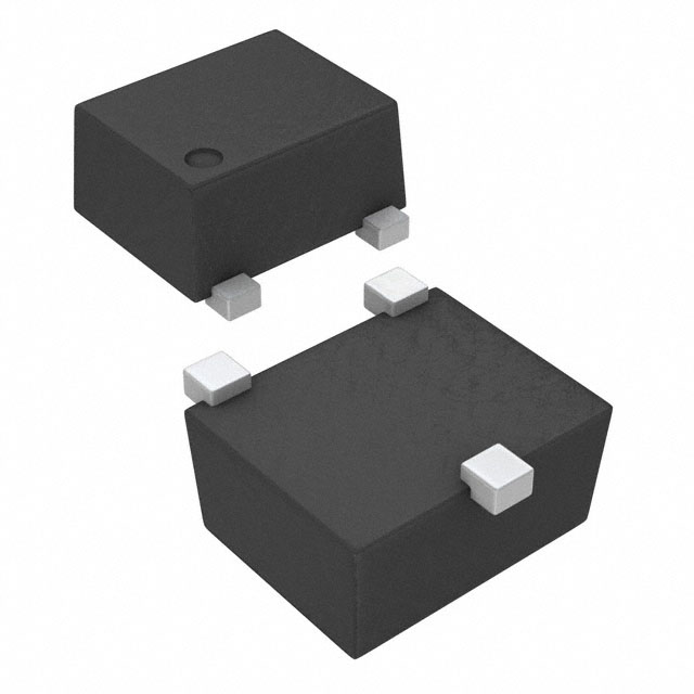
- Package Type: µSiP (SIL) 8-pin package (SIL0008E)
- Nominal Body Size: 3.50 mm × 3.50 mm, maximum height 1.75 mm
- Exposed Thermal Pad: Electrically connected to GND; mandatory soldering to PCB ground plane for thermal dissipation and mechanical reliability
- Status: Active (Production)
- RoHS Compliance: Yes
- Lead Finish/Ball Material: NIAU
- MSL Rating/Peak Reflow: Level-3-260°C-168 HR
- Operating Temperature Range: -40°C to 125°C (junction temperature)
- Part Marking: 1701 7485 EA (additional markings for logo/lot trace code/environmental category may apply in parentheses)
1.2 Ordering & Packaging Quantity
- Package Quantity (SPQ): 3000 units per carrier
- Carrier Type: LARGE Tape & Reel (T&R)
- Variant Reference: LMZ21701SILT (250 units, SMALL T&R; identical electrical specs, active production)
2. Tape & Reel Mechanical Dimensions (All nominal, unit: mm)
2.1 Reel Specifications
| Parameter | Value | Description |
|---|---|---|
| Reel Diameter | 330.0 | Standard large T&R reel size |
| Reel Width (W1) | 12.4 | Tape fit width on reel |
2.2 Carrier Tape Specifications
| Parameter | Value | Design Purpose |
|---|---|---|
| A0 | 3.75 | Accommodates component width |
| B0 | 3.75 | Accommodates component length |
| K0 | 2.2 | Accommodates component thickness |
| P1 | 8.0 | Pitch between successive cavity centers |
| W | 12.0 | Overall width of the carrier tape |
| Pin1 Quadrant | Q2 | Orientation of Pin 1 in tape pocket quadrants |
2.3 Tape & Reel Box Dimensions
表格
| Parameter | Value |
|---|---|
| Length | 383.0 |
| Width | 353.0 |
| Height | 58.0 |
3. PCB Layout, Land Pattern & Stencil Design Guidelines
3.1 Land Pattern Requirements (SIL0008E)
- Pad Sizing: 8×0.45 mm, 8×0.4 mm, 2×0.8 mm, 6×0.8 mm symmetric layout; 0.2 mm typical vias for thermal pad
- Solder Mask: 0.07 mm minimum clearance and 0.07 mm maximum offset on all sides; supports both solder mask defined (SMD) and non-solder mask defined (NSMD) patterns
- Copper Plane: Unbroken GND copper plane required for thermal performance and shielding; thermal vias to connect GND layers
- Pick-and-Place: Recommended nozzle size ≤1.3 mm for component placement
3.2 Stencil Design Specifications
- Base Stencil Thickness: 0.125 mm
- Solder Paste Coverage: 85% of the exposed thermal pad area (by area) for reliable soldering
- Aperture Design: Laser-cut apertures with trapezoidal walls and rounded corners (per IPC-7525 recommendations for optimal paste release)
- Aperture Sizing: 8×0.45 mm, 8×0.4 mm, 4×0.76 mm, 4×0.85 mm, 6×0.8 mm symmetric; 0.525 mm typical metal offset
3.3 Critical Layout Rules
- High di/dt Loop Minimization: Place input capacitor (CIN) as close as possible to VIN and GND pins; use wide, short copper traces for main current paths to reduce parasitic inductance.
- Sensitive Node Protection: Mount feedback resistor divider (RFBT/RFBB) directly at FB pin; use thin, short traces for VOS pin (add 0.1 µF capacitor from VOS to GND for high-noise systems).
- Thermal Design: Flood unused PCB area with GND copper; use 4-layer PCB (layers 2/4 as GND planes) for enhanced thermal dissipation and shielding (35 mm² single-sided solution size available for space-constrained applications).
- Component Sizing: 0805 case size for CIN/COUT; 0402 case size for passive components (CSS, resistors) for high-density layouts.
4. Thermal Characteristics & Design Requirements
4.1 Key Thermal Metrics (JEDEC 51-5, SIL0008E)
表格
| Thermal Metric | Value | Unit |
|---|---|---|
| RθJA (Junction-to-Ambient) | 42.6 | °C/W |
| RθJC(top) (Junction-to-Case, Top) | 20.8 | °C/W |
| RθJB (Junction-to-Board) | 9.4 | °C/W |
| ψJT (Junction-to-Top Characterization) | 1.5 | °C/W |
| ψJB (Junction-to-Board Characterization) | 9.3 | °C/W |
| RθJC(bot) (Junction-to-Case, Bottom) | 1.8 | °C/W |
4.2 Thermal Derating & Copper Area Requirements
- RθJA Dependence: Junction-to-ambient thermal resistance decreases with increased PCB copper area (4-layer board with 70 µm (2 oz) Cu has lower RθJA than 2-layer board at the same copper area).
- Required Copper Area Calculation: RθJA(required)≤(125∘C−TA)/PDISS, where TA = ambient temperature, PDISS = module power dissipation (refer to typical power dissipation curves in the datasheet).
- Max Junction Temperature: 125°C (continuous operation); thermal shutdown activates at 160°C (30°C hysteresis for recovery).
5. Mechanical Package Details (SIL0008E)
- Dimensioning Standard: ASME Y14.5M (all linear dimensions in millimeters; parenthetical values for reference only)
- Pin 1 Identification: Index area on package for Pin 1 alignment; pick area designated for placement equipment
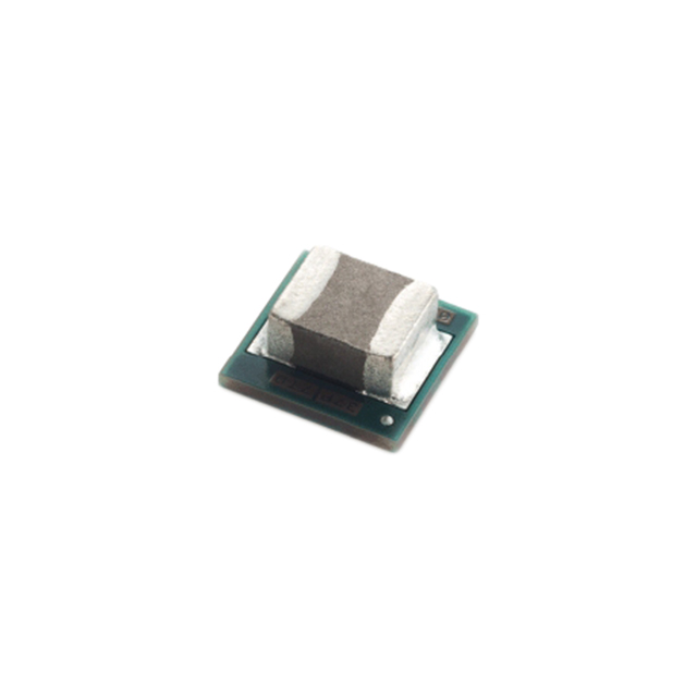
- Package Construction: FR-4 laminate substrate with embedded synchronous buck IC and surface-mounted 2.2 µH integrated inductor; bottom landing pads match 8-pin DFN footprint
- Mechanical Reliability: Thermal pad soldering is mandatory (refer to TI literature SLUA271 for detailed soldering guidelines)
6. Component Compatibility & Recommended External Parts
6.1 Mandatory External Components (Basic Operation)
- Input Capacitor (CIN): ≥10 µF (22 µF recommended), 25V rating, X7R/X5R MLCC (0805 case size)
- Output Capacitor (COUT): ≥10 µF (22 µF recommended), ≥10V rating, X7R/X5R MLCC (0805 case size)
- Soft-Start Capacitor (CSS): 3300 pF, ≥10V rating, X7R/X5R MLCC (0402 case size; minimum 1000 pF for monotonic VOUT ramp)
- Feedback Resistors (RFBT/RFBB): 1% tolerance, RFBB ≤400 kΩ (calculated via RFBT=RFBB×(VOUT/0.8−1))
- Power Good Pull-Up Resistor (RPG): 10 kΩ 1% (minimum RPG=VPULL−UP/2 mA per PG pin sink current)
6.2 Optional Components
- VOS Filter Capacitor: 0.1 µF MLCC (0402/0201) for high-noise environments
- Bulk Input Capacitor: ≥88 µF electrolytic (parallel to CIN) for long input cables (mitigates RLC oscillations and voltage drops)
7. Disclaimer & Document Revision Notes
7.1 Information Disclaimer
- All packaging/mechanical data is TI’s knowledge as of the release date (6-Feb-2026 for Packaging Addendum, 6-Jun-2025 for Package Materials) and is subject to change without prior notice.
- TI does not conduct destructive testing/chemical analysis on incoming materials; proprietary information (e.g., CAS numbers) may not be released.
- TI’s liability is limited to the total annual purchase price of the LMZ21701SILR units supplied to the customer.
7.2 Datasheet & Packaging Revision History
- Parent Datasheet (LMZ21701 SNVS853E): Revised August 2018 (Revision E); key updates include WEBENCH tool links, ESD rating renaming, and removal of Simple Switcher branding.
- Packaging Materials: Last updated October 2025; tape/reel dimensions and ordering specs are current as of this date.
- Package Drawing (SIL0008E): Subject to change without notice (TI drawing 4221554/B11/2014).
Purchase
No need to register to order from JMChip Electronics, but signing in lets you track your order like a pro. Give it a try for a smoother shopping ride.
Means
Easy peasy! Pay your way with PayPal, Credit Card, or wire transfer in USD. We've got you covered.
RFQ(Request for Quotations)
Get the freshest prices and stock updates by asking for a quote! Our sales team will shoot you an email within a day. It's that simple.
IMPORTANT NOTICE
1. Look out for your order details in your inbox! (If it's missing, check the spam folder just in case.)
2. Our sales manager will double-check the order and keep you posted on any price or stock changes. No worries, we've got you covered.

Shipping Rate
We ship orders once a day around 5 p.m., except Sunday. Once shipped, the estimated delivery time depends on the courier company you choose, usually 5-7 working days.

Shipping Methods
We provide DHL, FedEx, UPS, EMS, SF Express, and Registered Air Mail international shipping.


Payment
You can pay the orders on the website directly or pay by wire transfer offline. We support: Paypal、VISA、Credit Card.


Texas Instruments
Texas Instruments
Texas Instruments
Texas Instruments
Texas Instruments
Texas Instruments
Texas Instruments

Texas Instruments
Texas Instruments
Texas Instruments
Texas Instruments

Texas Instruments