Categories
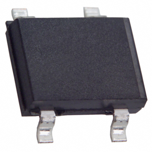
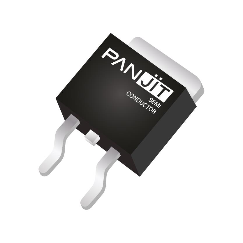
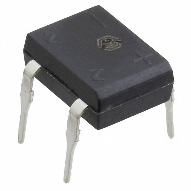
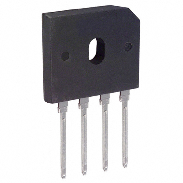
  • Bridge Rectifiers(100)
View Mode:result_1_0result_1_1result_2_0result_2_1
Email

Leave Us A Message!

We`re not around but we still want to hear from you! Leave us a note:

SEND
EmailWhatsApp
*You can contact us directly on WhatsApp!
  • img

    TS360ILS-AU_R1_000A1

    MICRO SURFACE MOUNT SCHOTTKY BRI

    Panjit International Inc.

  • img

    TS240S-AU_R1_000A1

    MICRO SURFACE MOUNT SCHOTTKY BRI

    Panjit International Inc.

  • img

    TS260S_R1_00001

    MICRO SURFACE MOUNT SCHOTTKY BRI

    Panjit International Inc.

  • img

    TS340IS_R1_00001

    MICRO SURFACE MOUNT SCHOTTKY BRI

    Panjit International Inc.

  • img

    TSM340IS_R1_00001

    MICRO SURFACE MOUNT SCHOTTKY BRI

    Panjit International Inc.

  • img

    GBJ2506ULV_T0_00601

    ULTRA LOW VF BRIDGE RECTIFIER WI

    Panjit International Inc.

  • img

    GBJ3510H_T0_00601

    GLASS PASSIVATED HIGH TJ 175 BRI

    Panjit International Inc.

  • img

    GBJ2510H_T0_00601

    GLASS PASSIVATED HIGH TJ 175 BRI

    Panjit International Inc.

  • img

    DI108_T0_00001

    DIP, GENERAL

    Panjit International Inc.

  • img

    DI108S_T0_00001

    SURFACE MOUNT GLASS PASSIVATED S

    Panjit International Inc.

  • img

    B108S_R2_00001

    MINI SURFACE MOUNT GLASS PASSIVA

    Panjit International Inc.

  • img

    GBU8MP_T0_00101

    GBU-1, GENERAL

    Panjit International Inc.

  • img

    GBU4MP_T0_00101

    GBU-1, GENERAL

    Panjit International Inc.

  • img

    KBP4M_T0_00101

    KBP, GENERAL

    Panjit International Inc.

  • img

    DI1010_T0_00001

    DIP, GENERAL

    Panjit International Inc.

  • img

    GBU6MP_T0_00101

    GBU-1, GENERAL

    Panjit International Inc.

  • img

    TS240S_R1_00001

    MICRO SURFACE MOUNT SCHOTTKY BRI

    Panjit International Inc.

  • img

    DI1510_T0_00001

    DIP, GENERAL

    Panjit International Inc.

  • img

    TS140S_R1_00001

    TDI, SKY

    Panjit International Inc.

  • img

    KBP2M_T0_00101

    KBP, GENERAL

    Panjit International Inc.

  • Total 100
    • 1
    • 2
    • 3
    • 4
    • 5

    What is a Rectifier?

    In the electronics industry, one of the most common uses of semiconductor diodes is to convert an alternating current (AC) signal, typically at 60 or 50 Hz, into a direct current (DC) signal. This DC signal can then be used to power electronic devices instead of relying on batteries. The circuit that performs this conversion is made up of a specific arrangement of diodes and is called a rectifier. In power supply circuits, two main types of rectifiers are widely used: half-wave and full-wave. Half-wave rectifiers allow only one half of the AC cycle to pass through, while full-wave rectifiers process both the positive and negative halves of the cycle, converting the negative half to match the polarity of the positive.

    Of the two types, the full-wave rectifier is more efficient because it utilizes the entire waveform cycle. There are two types of full-wave rectifiers: the center-tapped full-wave rectifier, which requires a center-tapped transformer, and the bridge rectifier, which operates without one. In this article, we will focus on the bridge rectifier, as it is the more commonly used option and often comes in preassembled modules, making it more convenient to implement.
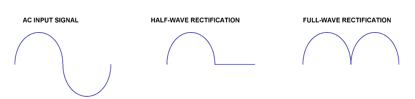
    Difference between outputs of half- and full- wave rectifiers

    How does a Bridge Rectifier work?

    Bridge rectifiers utilize four diodes arranged in a way that converts AC voltage to DC voltage. The output signal of this circuit maintains the same polarity, regardless of the polarity of the input AC signal.
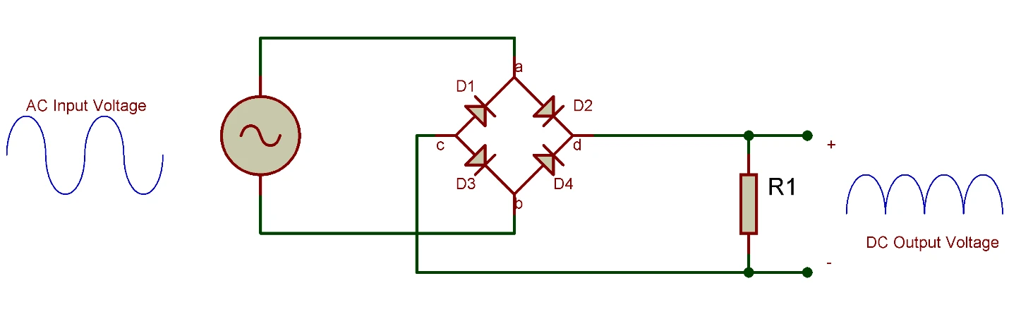
    Let’s examine how this rectifier circuit handles an AC signal with alternating polarities each cycle:

    During the positive half cycle of the AC signal, diodes D2 and D3 are forward biased and conduct current, while D1 and D4 are reverse biased and do not conduct. Current flows through the load resistor via the conducting diodes, resulting in a positive voltage at terminal d and a negative voltage at terminal c.

    In the negative half cycle, diodes D1 and D4 become forward biased while D2 and D3 are reverse biased. The anode of D4 receives positive voltage, and the cathode of D1 receives negative voltage. Importantly, the current through the load resistor flows in the same direction as it did during the positive half cycle. Thus, regardless of the input signal’s polarity, the output polarity remains consistent. Effectively, the negative half cycle of the AC signal is inverted, producing a positive voltage at the output.


    Filters
    ApplyReset All
    • Manufacturers
    • Stocking Options
    • Environmental Options
    • Current - Average Rectified (Io)
    • Current - Reverse Leakage @ Vr
    • Diode Type
    • Grade
    • Mounting Type
    • Operating Temperature
    • Package / Case
    • Qualification
    • Supplier Device Package
    • Technology
    • Voltage - Forward (Vf) (Max) @ If
    • Voltage - Peak Reverse (Max)
    Attribute column