
Instrumentation Amplifier vs a Current Sense Amplifier
Catalog
IntroductionCurrent Sense AmplifiersInstrumentation AmplifiersChoosing a DeviceWhy Low-Voltage from -48V Systems MattersFrequently Ask QuestionsRelated ArticlesIntroduction
Current sensing is a vital function across numerous electronic applications. Given the plethora of devices available, it's no wonder that selecting the right one can be perplexing, especially when deciding between an instrumentation amplifier and a current sense amplifier. While both can execute the current sensing function, achieving optimal cost and accuracy hinges on understanding their differences.
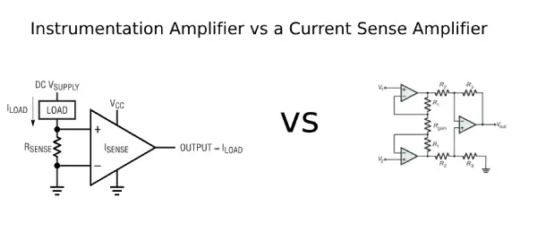
Instrumentation Amplifier vs a Current Sense Amplifier
Current Sense Amplifiers
A current sense amplifier (CSA) is a highly specialized device for current sensing. It operates based on Ohm's law. The CSA uses the voltage drop across a shunt resistor on the supply bus as input and converts it into an output signal proportional to the current flow, as illustrated in Figure 1.
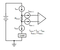
Figure 1. Simplified Current Measurement Application Utilizing a Shunt Resistor
The input signal can be amplified at the output through various available fixed gains. CSAs come with traditional analog outputs as well as digital outputs on devices that incorporate analog-to-digital converters (ADCs).
Instrumentation Amplifiers
An instrumentation amplifier (IA) is a monolithic, high-precision device that provides extremely high input impedance and common-mode rejection. The traditional three-operational-amplifier topology IA features a difference amplifier with buffered inputs, allowing the designer to set the gain across a wide range using a single resistor. The IA's output is a single-ended signal representing the difference between the two input signals. Unlike CSAs, IAs are versatile devices used in a wide range of applications beyond current sensing, such as pressure transmitters, weigh scales, analog input modules, hybrid/electric vehicles (HEV/EVs), and electrocardiograms (ECGs), among others. In place of specialization, IAs offer greater design flexibility.
Input Stage Topology
Although they share a similar operating principle in current sense applications, CSAs and IAs fundamentally differ in their input stage topology. CSAs employ a variety of unique input stage designs, such as common-base transistor inputs, which enable them to handle common-mode voltage (Vcm) levels significantly above and below the supply voltage. For instance, with a standard 5-V supply rail, they can manage Vcm levels as high as 120 V. However, this capability often comes at the cost of higher input bias current (Ibias) and lower input impedance. Additionally, CSAs may experience a rapid increase in Ibias as Vcm rises. While some newer devices offer improved specifications, typical CSAs have µA levels of Ibias and provide input impedance in the MΩ range.
In contrast, the buffered input of an IA offers input impedance in the hundreds of GΩ range and Ibias in the nA range, with minimal variation across Vcm. The trade-off for this high input impedance is a limitation in the Vcm range, which is usually within a few hundred millivolts to a couple of volts of each supply. To design a robust current measurement system, it is crucial to consider the constraints imposed by Ibias, Vcm range, and inherent error sources.
Input Bias Current Implications
Input bias current is the current that flows into the input transistors of a device. This specification is particularly important when measuring current, as it determines the potential use cases for a specific device. A large Ibias can reduce the supply bus current (Ibus) that needs to be measured. Ideally, the current flowing through the shunt resistor (Ishunt) should equal Ibus, but instead, it is determined by Equation 1.
The reduction of Ibus can create a significant measurement error, especially when Ibus is small, making it the primary limitation for measuring very small currents. Figure 2 illustrates how the error contribution from Ibias decreases as Ibus increases. Moreover, Ibias can vary not only with Vcm, as previously mentioned, but also with temperature.
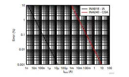
Figure 2. Percentage Error Resulting from Maximum Input Bias Current Compared to Supply Bus Current
Common-Mode Voltage Implications
Like Ibias, the Vcm range will dictate the application for a specific device. High-side and low-side current sensing usually expose the sensing device to Vcm values roughly equivalent to the supply bus voltage and ground, respectively. These conditions are particularly crucial when the sensing device's supply voltages are restricted. All devices must operate within the recommended Vcm range to prevent incorrect measurements. Once Ibias and Vcm requirements are satisfied, it is essential to consider input offset voltage and gain error, as they are likely to be the primary sources of error in the desired measurement.
Error Sources
Input offset voltage (Vos) is significant when dealing with small voltage drops across the shunt resistor (Vshunt). A small Vshunt is typical since shunt resistors must be kept as small as possible to limit load disturbance and power dissipation. At large Vshunt values, the impact of Vos diminishes, and gain error (GE), which remains constant regardless of Vshunt, becomes the dominant source of error, as shown in Figure 3. Essentially, Ibias, Vos, and GE will determine the lower bound of current measurement achievable by the device within the target accuracy. Similar to Ibias, Vos and GE will also drift with temperature, so it is important to consider the operating conditions. Consideration for common-mode rejection, power supply rejection, and noise is also important for accurate results. A more thorough analysis would involve the root sum square of all error sources. For a comprehensive error analysis on IAs, refer to the Comprehensive Error Calculation for Instrumentation Amplifiers tech note.
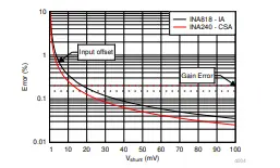
Figure 3. Percentage Error Resulting from Maximum Input Offset Voltage and Maximum Gain Error Relative to Shunt Resistor Voltage
Choosing a Device
In current sense applications where the load supply bus voltage exceeds the sensing device's supply voltage, a CSA may be necessary due to the IA's limited Vcm range. The size and cost of the system should also be considered, as CSAs are generally available in smaller packages and at a lower cost. Conversely, if the current to be measured is expected to be very small, an IA will typically be a good choice given its low Ibias, Vos, and GE. An IA will also be attractive for designs that require flexible gain and higher bandwidth (BW), as CSAs typically offer fixed gain and lower BW. To summarize, when selecting a device for a current sensing application, it is important to consider the error, size, and cost of the system, as well as the expected Ibus, Vcm, and BW range of the application.
Table 1. Instrumentation and Current Sense
Amplifier Summary
| Instrumentation Amplifier | Current Sense Amplifier | |
|---|---|---|
| Ibus sense | nA to 10s of amps | mA to 10s of amps |
| Vcm range | Vs (–) to Vs (+) | Independent of supply |
| Strengths | Sensing small currents Flexible gain Range of applications High accuracy | Wide Vcm range Specialized integration Small package sizes Cost |
| Challenges | Vcm limitations | Small current sense |
Be sure to check out the training video series on Instrumentation Amplifiers and Current Sense Amplifiers.
Table 2. Recommended Devices
| Instrumentation amplifiers | INA333-Q1 : 25-μV, 0.1-μV/°C, 0.2-nA Ibias, 0.25% GE INA818 : 2-MHz, 35-μV, 8-nV/√ Hz, 0.15-nA Ibias, 0.15% GE | INA819 : 2-MHz, 35-μV, 8-nV/√ Hz, 0.15-nA Ibias, 0.15% GE INA821 : 4.7-MHz, 35-μV, 7-nV/√ Hz, 0.15% GE |
|---|---|---|
| Current sense amplifiers | INA186 : 50-μV, 0.5-nA Ibias, 1% GE, –0.2 V to +40 V Vcm INA185 : 55-μV, tiny package, –0.2 V to +26 V Vcm | INA293-Q1 : 200-μV, 20-µA Ibias, 0.2% GE –4 V to +110 V Vcm INA240 : 25-μV, 90-µA Ibias, 0.2% GE, –4 V to +80 V Vcm |
Why Low-Voltage from -48V Systems Matters
To safeguard telephone wires against electrolytic corrosion, the initial telephone-system exchanges utilized a "central-battery" power supply with a negative polarity relative to ground (earth). Additionally, to ensure reliable low-noise contacts in the relays used in these systems, the supply voltage (-48V) was set higher than that of most other battery-powered systems.
However, since the early 1960s, electronics systems have taken a different path. Driven by the prevalence of npn bipolar transistors as the primary active devices, nearly all power supplies for contemporary analog and digital systems produce voltages that are positive with respect to the reference equipotential (ground).
Despite this shift, the majority of today's telecom power is still distributed and utilized in a manner similar to the early days, with -48V remaining the primary power source, backed up by substantial battery arrays. Meanwhile, modern telecom systems, which are now entirely electronic, require low-voltage positive power-supply lines. Consequently, generating low-voltage positive power from -48V systems has become a common necessity.
Frequently Ask Questions
What is the difference between an amplifier and an instrumentation amplifier?
INAs are distinguished from other amplifiers by three main characteristics: gain set by a single external resistor, an input buffer stage, and an output difference amplifier stage.
What is a current sense difference amplifier?
A current sense amplifier is a differential amplifier that provides an analog output voltage proportional to the current flowing through a load connected to its input.
What is the advantage of an instrumentation amplifier?
An instrumentation amplifier (IA) is designed to amplify very low-level signals significantly, often in noisy environments. Key features of IAs include high gain, a large common-mode rejection ratio (CMRR), and very high input impedance.
What are the drawbacks of an instrumentation amplifier?
- Noise can be superimposed on the original signal during long-range transmission, which can be mitigated by using specialized noise-reducing cables.
- There is a limitation on the strength of the input signal.
- When to use an instrumentation amplifier? Instrumentation amplifiers, due to their high common-mode rejection, are often used in audio applications (e.g., as microphone preamps), to extract weak signals from noisy environments, and to minimize offsets and noise caused by ground loops.
What are the three types of amplifiers?
- Voltage amplifiers take voltage as input and produce a voltage output.
- Current amplifiers receive a current input and produce a current output.
- Transconductance amplifiers convert a voltage input to a current output.
- Transresistance amplifiers convert a current input to a voltage output.
What are the advantages of a sense amplifier?
This enables robust current measurements across the entire specified temperature range. Temperature stability is a key advantage that current sense amplifiers have over discrete implementations. Current sensing techniques involve placing the current sense element between the supply bus and the load.
Related Articles

Christopher Anderson
Christopher Anderson has a Ph.D. in electrical engineering, focusing on power electronics. He’s been a Senior member of the IEEE Power Electronics Society since 2021. Right now, he works with the KPR Institute of Engineering and Technology in the U.S. He also writes detailed, top-notch articles about power electronics for business-to-business electronics platforms.
Subscribe to JMChip Electronics !