
Introduction to Single-phase Induction Motors
Catalog
Single Coil of a Single-Phase MotorPermanent-Split Capacitor MotorCapacitor-Start Induction MotorCapacitor-Run Induction MotorResistance Split-Phase Induction MotorNola Power Factor CorrectorSummary: Single-Phase Induction MotorsFrequently Asked QuestionsRelated ArticlesA three-phase motor can actually run on a single-phase power source, but it won’t start on its own. It can be hand-started in either direction and will get up to speed in just a few seconds. However, it will only produce 2/3 of the power it would normally generate from three-phase power, since one of the windings isn't used.
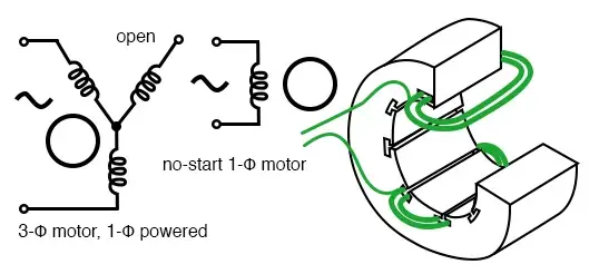
3-φ motor runs from 1-φ power but does not start
Single Coil of a Single-Phase Motor
The single coil in a single-phase induction motor doesn't create a rotating magnetic field. Instead, it makes a pulsating field that reaches its maximum intensity at 0° and 180° electrical.
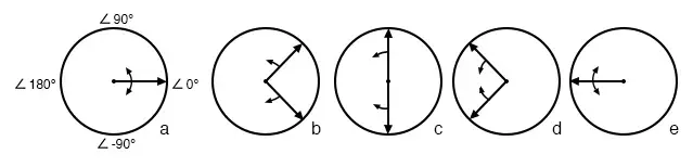
Single-phase stator produces a nonrotating, pulsating magnetic field
You can also think of it this way: The coil, when powered by single-phase current, creates two counter-rotating magnetic field phasors. These phasors meet twice during a rotation—once at 0° (like in the first diagram) and again at 180° (like in the last diagram). When the phasors reach 90° and -90°, they cancel each other out (like in the third diagram).
At 45° and -45° (the second diagram), the phasors are partly additive along the +x axis but cancel out along the y-axis. Something similar happens in the fourth diagram. The two phasors add up to create a stationary phasor, but its polarity changes over time. This means there's no starting torque generated.
But, if you manually start the rotor just a bit slower than the synchronous speed, it will create maximum torque at 10% slip (compared to the forward rotating phasor). Less torque is produced if the slip is either higher or lower than 10%.
For the counter-rotating magnetic field phasor, the rotor experiences 200% - 10% slip, but it doesn't create much torque from it (you can see this in the torque vs slip curve). Most of the torque comes from the forward rotating phasor once the rotor gets going.
If the rotor is started in the reverse direction, it will also develop a large amount of torque as it gets closer to the speed of the backward rotating phasor.
Just like polyphase induction motors, single-phase induction motors have a copper or aluminum squirrel cage inside a steel laminated cylinder.
Permanent-Split Capacitor Motor
One way to fix the single-phase problem is to create a 2-phase motor by getting 2-phase power from a single-phase supply. This involves a motor with two windings that are spaced 90° apart (electrically) and powered by two phases of current that are 90° apart in time. This type of motor is called a permanent-split capacitor motor.
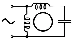
Permanent-split capacitor induction motor
But, this motor does come with some issues—it has increased current and a delay in the timing as it speeds up, plus there are torque pulsations when it's running at full speed. The trick to fixing this is to use a small capacitor (impedance) to keep losses to a minimum.
The losses are actually less than what you’d get with a shaded pole motor. This setup works pretty well for motors up to about 1/4 horsepower (200 watts), so it’s usually found in smaller motors. To change the direction of the motor, you just switch the capacitor into the other winding. This type of motor can also be used as a servo motor, which is explained elsewhere in this chapter.
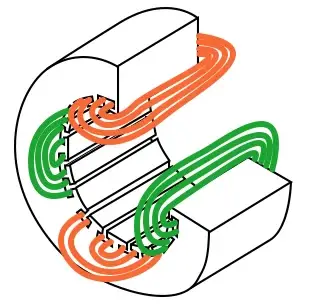
Single-phase induction motor with embedded stator coils
Single-phase induction motors can have coils built into the stator for the larger motors. But for the smaller ones, they usually use simpler, concentrated windings with salient poles, which are easier to build.
Capacitor-Start Induction Motor
In the diagram below, a bigger capacitor is used to start a single-phase induction motor through the auxiliary winding. Once the motor gets up to speed, a centrifugal switch kicks in and takes the capacitor out of the circuit. Also, the auxiliary winding in this setup might have a lot more turns and use heavier wire compared to a resistance split-phase motor, which helps avoid overheating.
The result? More starting torque is available, which is perfect for heavier loads like air conditioning compressors. This motor setup works so well that you can find it in multi-horsepower (or multi-kilowatt) versions.
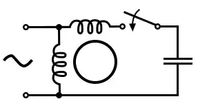
Capacitor-start induction motor
Capacitor-Run Induction Motor
One variation of the capacitor-start motor (see below) is the capacitor-run motor. In this setup, the motor is started with a larger capacitor for high starting torque, but after it starts, a smaller capacitor stays in place to improve the running characteristics without drawing too much current. The added complexity of this design is worth it for larger motors.
A motor starting capacitor could be a double-anode non-polar electrolytic capacitor, which is basically two polarized electrolytic capacitors (+ to + or - to -) connected in series. These electrolytic capacitors have high losses, so they’re only used for short bursts (like 1 second on, 60 seconds off) for motor starting.
For running, the capacitor must be a lower-loss polymer type, not an electrolytic one.
Resistance Split-Phase Induction Motor
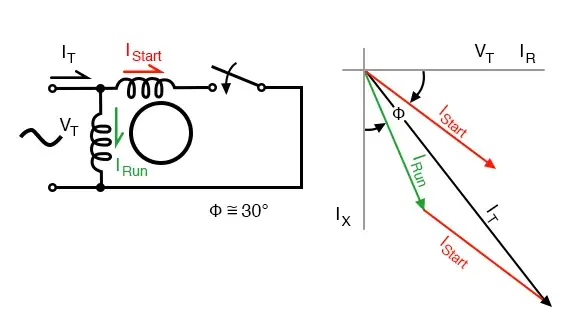
If you place an auxiliary winding with fewer turns and smaller wire at a 90° electrical angle to the main winding, it can start a single-phase induction motor. With lower inductance and higher resistance, the current in the auxiliary winding shifts less compared to the main winding.
This gives about 30° of phase difference. The coil provides moderate starting torque and is disconnected by a centrifugal switch when the motor reaches about 3/4 of synchronous speed. This simple setup (without a capacitor) works well for motors up to 1/3 horsepower (250 watts) that drive loads that are easy to start.
Resistance split-phase motor induction motor
This motor has more starting torque than a shaded pole motor (we'll get into that in the next section), but not as much as a two-phase motor built from the same parts. The current density in the auxiliary winding is so high when starting that the rapid temperature rise makes it unsuitable for frequent restarts or slow starting loads.
Nola Power Factor Corrector
Back in the mid-1970s, Frank Nola from NASA came up with a power factor corrector to improve the efficiency of AC induction motors. The idea is that induction motors are less efficient when they're not running at full load, and this inefficiency shows up as a low power factor.
The low power factor comes from the magnetizing current needed by the stator. This current stays fixed, but as the motor load decreases, it becomes a bigger chunk of the total current. At light loads, the full magnetizing current isn't necessary, so it could be reduced by lowering the applied voltage, which would help improve both the power factor and efficiency.
The power factor corrector senses the power factor and lowers the motor voltage, which improves the power factor and reduces losses.
Single-phase motors are usually 2 to 4 times less efficient than three-phase motors, so there’s potential for energy savings with 1-φ motors. But if the motor is fully loaded, there's no benefit because all the stator magnetizing current is needed.
However, if the motor isn’t fully loaded, there’s potential savings. For example, a motor designed for 117 VAC can actually run on anywhere from 104 to 127 VAC. So, if the voltage is above 104 VAC, the motor is not fully loaded, like in the case of a 117 VAC refrigerator.
It’s safe for the power factor controller to lower the voltage to around 104-110 VAC. The higher the initial line voltage, the more savings you can get. Of course, if the power company delivers closer to 110 VAC, the motor will run more efficiently without needing any extra devices.
Any single-phase induction motor that’s mostly idle (around 25% of its full-load current or less) is a good candidate for a power factor controller, especially if it runs for a lot of hours each year. The more time it spends idling—like a lumber saw, punch press, or conveyor—the more likely it is that the power factor controller will pay for itself in a few years.
It should be easier to break even with this controller, about three times faster compared to a more efficient 3-φ motor. But if the motor only runs a few hours a day, you probably won’t recover the cost of the power factor corrector.
Summary: Single-Phase Induction Motors
- Single-phase induction motors can’t start on their own without an auxiliary stator winding powered by an out-of-phase current of about 90°.
- In a permanent split capacitor motor, the auxiliary winding has a capacitor in series with it during both starting and running.
- A capacitor-start induction motor only uses a capacitor in series with the auxiliary winding when starting.
- A capacitor-run motor has a large non-polarized electrolytic capacitor in series with the auxiliary winding for starting, then switches to a smaller non-electrolytic capacitor during running.
- In a resistance split-phase motor, the auxiliary winding develops a phase difference compared to the main winding during starting because of the resistance difference.
Frequently Asked Questions
What is a single-phase induction motor?
Single-phase induction motors are simple motors that run on single-phase AC power. They produce torque because of the induction of electricity, which is caused by alternating magnetic fields. These motors come in different types depending on how they start and other factors.
What are the disadvantages of a single-phase induction motor?
- For the same frame size and temperature, the output is only about 50% of what you'd get from a three-phase induction motor.
- They can’t start on their own (they’re not self-starting).
- These motors tend to have a lower power factor.
- They are less efficient.
- They don’t have any starting torque.
Is a single-phase induction motor AC or DC?
An induction motor, or asynchronous motor, is an AC electric motor. The electric current that creates the torque in the rotor is induced by the magnetic field from the stator winding.
What is the difference between a single-phase induction motor and a synchronous motor?
The main difference is that in a synchronous motor, the rotor speed is equal to the stator speed. But in an induction motor, the rotor speed is always less than the synchronous speed.
What is the problem with single-phase motors?
Most issues with single-phase motors are related to the centrifugal switch, thermal switch, or capacitor(s). When there's a problem with one of these components, the motor can usually be repaired and serviced.
Related Articles
What Stepper Motor IS & How It Works
VCU Solution for Electric Motorcycles Using STM32G0B1VCT6
Analysing Signs of Damage to Motorcycle Voltage Regulators

Amanda Miller
Amanda Miller is a senior electronics engineer with 6 years of experience. She focuses on studying resistors, transistors, and package design in detail. Her deep knowledge helps her bring innovation and high standards to the electronics industry.
Subscribe to JMChip Electronics !