
What Is A Solid State Relay?
Catalog
What is a solid state relay?Solid State Relay Working PrincipleHow does a solid state relay work?Types of Control for Solid State RelaysChoosing an solid state relay(SSR)A key component found in electrical panels is the relay, with many people familiar primarily with standard electromechanical relays. However, there's another widely used type of relay, especially for heavy and resistive loads: the solid state relay (SSR). In this post, we will explore the fundamental concept of a solid state relay.
What is a solid state relay?
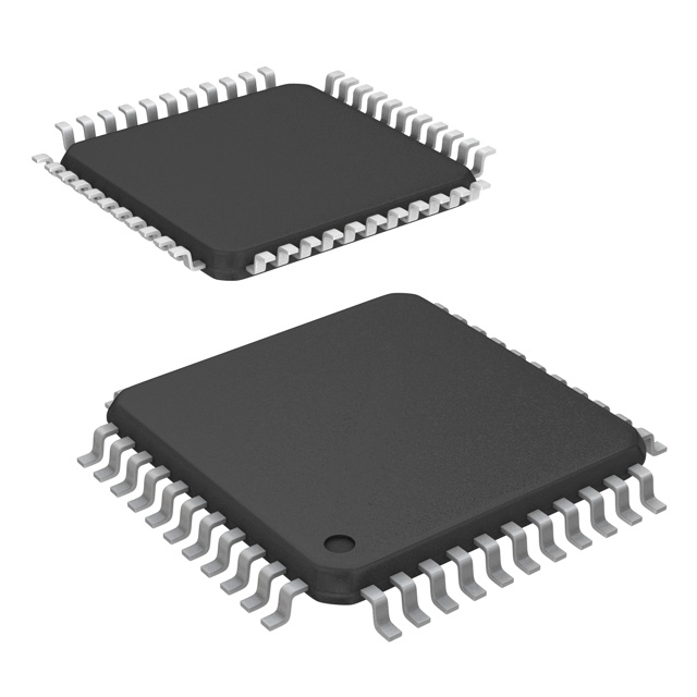
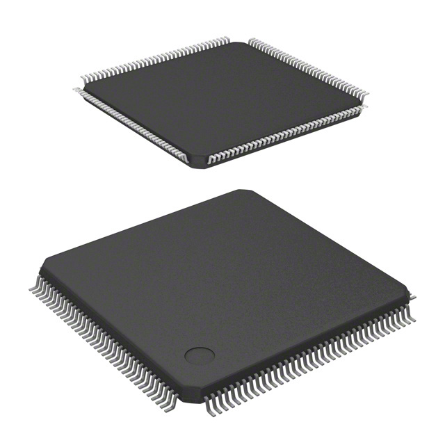
As its name suggests, a solid state relay (SSR) operates using semiconductors. Unlike electromechanical relays that rely on mechanical contacts to switch circuits on or off, SSRs contain no mechanical parts. Instead, switching occurs rapidly through semiconductors such as triacs, transistors, diodes, and thyristors. This technology utilizes infrared light-emitting diodes or LED couplers for operation, enabling much faster switching compared to traditional electromechanical relays. Additionally, SSRs can accommodate a wide range of control voltages, both fixed and variable, thanks to their semiconductor design. They are primarily used for resistive and heavy loads, such as heaters and heat tracing systems, which require substantial current.
Solid State Relay Working Principle
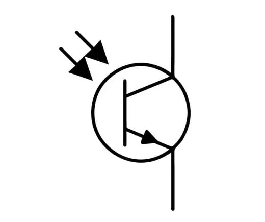
Refer to the figure below. As mentioned earlier, solid state relays (SSRs) lack moving components. They are made up of semiconductors and electronic elements.
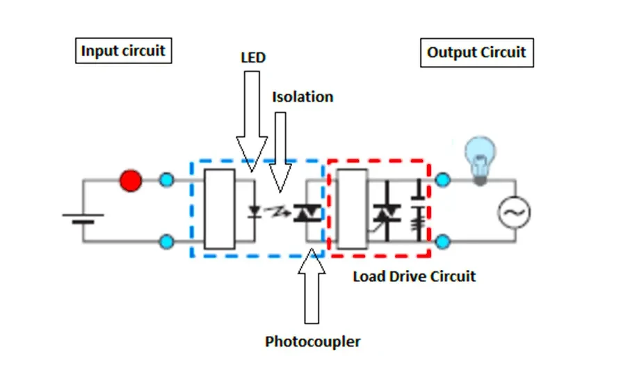
The input circuit features an LED that is activated by the input voltage, providing isolation between the input and output circuits. The output circuit includes a photo-coupler that captures the emitted light and converts it into electrical energy for the load drive circuit, which may consist of triacs, diodes, transistors, or thyristors.
When power is supplied to the input circuit, current flows through the LED, causing it to emit light. The photo-coupler detects this light and transforms it into an electrical voltage, which is then sent to the load drive circuit to regulate the final output voltage to the load. When the input voltage is turned off, the load also shuts down.
Thanks to opto-coupling technology, switching is rapid, sensitive, and offers high insulation levels. The output voltage can be either digital or analog, depending on the configuration of the input circuit and load drive circuit used.
How does a solid state relay work?
You might be curious about how a switch can control signals for hundreds of amperes. The real advantage of solid state relay design over electromechanical relay design lies in the differences in their switching mechanisms. Solid state relays utilize components known as opto-isolators or opto-couplers, essentially functioning as “light-separators.” That’s correct—the switch within a solid state relay operates using a beam of light! Typically, a low-power LED emits light onto a photodiode, which almost instantly enables power transmission through it, effectively “switching” it on.
Opto-isolators play a vital role in solid state relay design by providing separation between the various circuits of the relay. Since relays utilize low-voltage signals to control much larger voltage signals, maintaining this separation is crucial. The remarkable feature of opto-isolators is that they have no moving parts. In contrast, electro-mechanical relays achieve circuit separation through an electromagnetic field, which also helps complete the high-load circuit.
In a solid state relay, the photodiode is responsible for completing the connection within the load circuit. So, what exactly is a photodiode? It’s a specialized type of transistor that uses photons to activate the gate instead of a conventional electrical signal. This process is made possible by a highly specialized silicon P-N junction.
Types of Control for Solid State Relays
There are three types of control methods available for solid state relays (SSR).
They are as follows
- Random Turn-On of Solid State Relay
- Zero crossing of Solid State Relay
- Proportional Control of Solid State Relay
Choosing an solid state relay(SSR)
Identify your voltage
First, identify whether you need to switch AC or DC voltage. The electrical grid and wall outlets supply AC, while batteries and most small power supplies provide DC.
Next, assess the maximum voltage you'll be switching. For DC, especially with batteries, expect the voltage to be at least 25% higher than the rated value of the battery. AC voltage can fluctuate even more, but AC solid-state relays (SSRs) are built to manage these surges. In North America, the typical wall outlet voltage is 110VAC, while in Europe it is usually 220VAC. Ensure you know the standard voltage for your country when switching AC from a wall socket.
Identify your current
The current drawn by your load when activated influences the size of the solid-state relay (SSR) you need and its operating temperature. If you know the average current your load consumes, this is termed Average Load Current. If you're unaware of the average current but know the wattage (power rating) of your load, you can calculate Average Load Current using the formula:
【Average Load Current = Watts / Operating Voltage】
Next, it's important to determine the current drawn by your load during startup. Many loads experience a significant inrush of current when initially turned on, which can place considerable stress on the SSR's electronics. For instance, if you've noticed lights dimming momentarily when the furnace starts, it's due to the fan motor drawing a large amount of current at startup. Just as moving a heavy object from rest requires a lot of force, powering up a fan or incandescent bulb demands a substantial initial current. Measuring the Surge Current directly can be challenging, so we often use a multiplier based on the type of device. Surge Current is also known as inrush current.
| Application | Multiplier |
|---|---|
| Incandescent Light Bulbs | 6x |
| Motors | 6x |
| LEDs | 1x |
| Complex Electronics i.e., Motor Controllers, Phidgets | 6x |
| Fluorescent Light Fixtures (AC Only) | 10x |
| Transformers | 20x |
| Heaters | 1x |
Multiply your Average Load Current by the multiplier for your device type to calculate the Surge Current.

Christopher Anderson
Christopher Anderson has a Ph.D. in electrical engineering, focusing on power electronics. He’s been a Senior member of the IEEE Power Electronics Society since 2021. Right now, he works with the KPR Institute of Engineering and Technology in the U.S. He also writes detailed, top-notch articles about power electronics for business-to-business electronics platforms.
Subscribe to JMChip Electronics !