
Introduction to Insulated Gate Bipolar Transistor
The Insulated Gate Bipolar Transistor, or IGBT for short, is kind of a mix between a regular Bipolar Junction Transistor (BJT) and a Field Effect Transistor (MOSFET). This makes it perfect for use as a semiconductor switching device.
The IGBT takes the best features from these two types of transistors: the high input impedance and fast switching speeds of a MOSFET, along with the low saturation voltage of a BJT. It combines them to create a new type of transistor that can handle large collector-emitter currents with almost no gate current needed.
In simple terms, the IGBT uses the "insulated gate" (that’s where the first part of its name comes from) technology from the MOSFET, and mixes it with the performance of a regular bipolar transistor (that’s the second part of its name).
This hybrid design means the IGBT has the switching and conduction characteristics of a BJT, but it’s voltage-controlled like a MOSFET. IGBTs are mainly used in power electronics, like inverters, converters, and power supplies, where regular power BJTs and MOSFETs don’t fully cut it. While high-current and high-voltage BJTs exist, they’re slow to switch. Power MOSFETs are faster, but high-voltage and high-current ones are expensive and hard to find.
The real advantage of an IGBT over a BJT or MOSFET is that it offers more power gain than a regular BJT, along with the higher voltage operation and lower input losses of the MOSFET. Basically, it’s like combining an FET and a BJT into a sort of Darlington-type configuration.
Insulated Gate Bipolar Transistor
Insulated Gate Bipolar Transistor
The insulated gate bipolar transistor (IGBT) is a three-terminal transconductance device. It combines an insulated gate N-channel MOSFET input with a PNP bipolar transistor output, set up in a type of Darlington configuration.
Because of this, the terminals are labeled as: Collector, Emitter, and Gate. Two of these terminals (C-E) are part of the conductance path where current flows, while the third terminal (G) controls the device.
The amplification achieved by the IGBT is the ratio between the output signal and the input signal. For a regular BJT (Bipolar Junction Transistor), the gain is roughly the ratio of output current to input current, which is called Beta.
In a MOSFET (Metal Oxide Semiconductor Field Effect Transistor), there’s no input current since the gate is isolated from the main current path. So, the gain of a MOSFET is based on the ratio of the change in output current to the change in input voltage, making it a transconductance device. This is also true for the IGBT. You can think of the IGBT as a power BJT, but with its base current supplied by a MOSFET.
The IGBT can be used in small signal amplifier circuits, just like BJTs or MOSFETs. But what makes the IGBT stand out is that it combines the low conduction loss of a BJT with the high switching speed of a power MOSFET, making it a great solid-state switch for power electronics applications.
The IGBT also has much lower "on-state" resistance (RON) compared to a MOSFET. This means the I²R loss across the bipolar output structure for a given switching current is much smaller. Its forward blocking operation is similar to a power MOSFET.
When used as a static controlled switch, the IGBT has voltage and current ratings similar to a BJT. However, thanks to its isolated gate, it’s much easier to drive than a BJT, since it requires much less drive power.
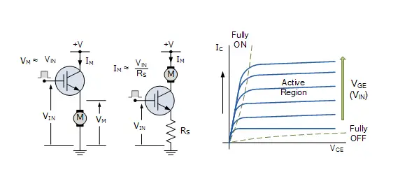
An insulated gate bipolar transistor is simply turned “ON” or “OFF” by controlling its Gate terminal. When you apply a positive voltage between the Gate and the Emitter, the device stays in its “ON” state. But if you make the input gate signal zero or slightly negative, it’ll turn “OFF,” just like a bipolar transistor or an eMOSFET.
One more advantage of the IGBT is that it has much lower on-state channel resistance compared to a regular MOSFET.
IGBT Features
IGBT
Since the IGBT is a voltage-controlled device, it only needs a small voltage at the Gate to keep current flowing through the device. This is different from BJTs, which need a continuous supply of Base current to stay in saturation.
Also, the IGBT is a unidirectional device, meaning it can only switch current in the “forward direction”—from Collector to Emitter. This is different from MOSFETs, which can switch current in both directions (forward is controlled, reverse is uncontrolled).
The way an IGBT works and the Gate drive circuits are similar to an N-channel power MOSFET. The key difference is that the resistance in the conducting channel when the IGBT is “ON” is much smaller, which means it can handle much higher current compared to a similar power MOSFET.
The main benefits of using an IGBT over other transistor types include its high voltage capability, low ON-resistance, easy drive, relatively fast switching speeds, and zero gate drive current. This makes it a great option for applications like pulse-width modulation (PWM), variable speed control, switch-mode power supplies, or solar-powered DC-AC inverters and frequency converters, especially in the hundreds of kilohertz range.
A general comparison between BJTs, MOSFETs, and IGBTs is shown in the table below.
IGBT Comparison Table
| Device Characteristic | Power Bipolar | Power MOSFET | IGBT |
| Voltage Rating | High <1kV | High <1kV | Very High >1kV |
| Current Rating | High <500A | Low <200A | High >500A |
| Input Drive | Current, hFE 20-200 | Voltage, VGS 3-10V | Voltage, VGE 4-8V |
| Input Impedance | Low | High | High |
| Output Impedance | Low | Medium | Low |
| Switching Speed | Slow (uS) | Fast (nS) | Medium |
| Cost | Low | Medium | High |
We’ve seen that the Insulated Gate Bipolar Transistor (IGBT) is a semiconductor switching device that has the output characteristics of a bipolar junction transistor (BJT), but it’s controlled like a metal oxide field effect transistor (MOSFET).
One of the main advantages of the IGBT is how easily it can be turned “ON” by applying a positive gate voltage, or switched “OFF” by making the gate signal zero or slightly negative. This makes it perfect for all kinds of switching applications. It can also be used in its linear active region for power amplifiers.
Thanks to its lower on-state resistance and conduction losses, plus its ability to switch high voltages at high frequencies without getting damaged, the IGBT is ideal for driving inductive loads like coil windings, electromagnets, and DC motors.
Related Articles
Introduction to Optical Comparators
Introduction to Mechanical Comparator
Buck vs Boost Converter: A Comparison

Christopher Anderson
Christopher Anderson has a Ph.D. in electrical engineering, focusing on power electronics. He’s been a Senior member of the IEEE Power Electronics Society since 2021. Right now, he works with the KPR Institute of Engineering and Technology in the U.S. He also writes detailed, top-notch articles about power electronics for business-to-business electronics platforms.
Subscribe to JMChip Electronics !