
Introduction to Flexible Alternating Current Transmission
Catalog
Theory of Flexible Alternating Current TransmissionTypes of FACTS DevicesSeries Compensation DevicesPhase Angle CompensationFrequently Asked QuestionsRelated ArticlesA Flexible Alternating Current Transmission System (FACTS) is basically a group of power-electronic devices designed for use in AC transmission systems. These devices help improve and manage power flow and voltage support. They’re great alternatives to traditional upgrades for electric grids, especially when building new transmission lines or substations isn’t practical or cost-effective.
Flexible Alternating Current Transmission
So, how do FACTS devices work their magic? They generally enhance power and voltage in three main ways:
Shunt Compensation: They act like capacitors or inductors to help with voltage.
Series Compensation: They substitute for series capacitors to manage impedance.
Phase-Angle Compensation: They take over roles like generator droop control or phase-shifting transformers.
While traditional equipment can handle these tasks, FACTS devices use power electronics that switch super fast, working within sub-cycles rather than taking seconds or minutes. Most FACTS devices are dynamic, meaning they can adjust voltage across a range instead of just being on or off. Plus, they’re multi-quadrant, so they can supply and absorb reactive power, and sometimes even real power! That’s what makes them so "flexible" and perfect for situations where needs can change.
The FACTS family actually came from advances in High-Voltage Direct-Current (HVDC) conversion and transmission. HVDC focused on turning AC into DC for big, manageable power transfers. While HVDC dealt with AC to DC, FACTS devices used that tech to help regulate power and voltage in AC systems. The Static VAR Compensator (SVC) is the most common FACTS device, using Thyristors to switch and manage shunt capacitors and reactors.
Back in the day, Synchronous Machines were used as generators and could offer some reactive power support, but they had their limits with increased losses. As we extended higher voltage lines farther from power sources, they became less efficient. To tackle this, they used fixed shunt capacitor and reactor banks in strategic spots. Shunt capacitors were switched by circuit breakers to manage varying reactive power demands from changing loads. But this method had its downsides.
Shunt capacitors and reactors are pretty much fixed, so they can only be turned on or off. This meant they needed careful sizing studies or accepted not-so-great effects on transmission line voltages. Realizing there had to be a better way, the mercury-arc valve was introduced in the early 20th century. These high-powered rectifiers could convert high AC voltages to DC, and with tech advancements, they could also invert power, making them useful in power systems and HVDC connections. Pairing them with reactors allowed for different switching patterns that could change the effective connected inductance, giving more dynamic control. They stayed in the spotlight until solid-state semiconductors came along in the mid-20th century.
With semiconductors replacing vacuum tubes, the thyristor changed the game for modern FACTS devices, like the Static VAR Compensator (SVC). It acts like a super-fast circuit breaker, turning capacitor banks on and off in a millisecond. When combined with a reactor and switched at sub-cycle intervals, it allowed for adjustable effective inductance. Plus, the thyristor greatly improved control systems, enabling SVCs to quickly spot and react to faults for better system support. The thyristor was a key player in the FACTS and HVDC world until the late 20th century when IGBTs started to catch up with its power ratings.
Theory of Flexible Alternating Current Transmission
The basic theory behind how FACTS devices affect the AC transmission system is all about looking at power transfer between two points in the AC grid. This analysis is super important for understanding how an AC electrical grid operates, especially since it has lots of nodes (like substations) that sometimes don’t have enough sources (like generators) or loads. It’s key to calculate and manage power flow at each node (or substation bus) to make sure the grid’s design and layout don’t mess up the delivery of generated electricity to where it’s needed. This gets really crucial when Transmission Lines stretch for miles, sometimes even hundreds, which can cause significant impedance and voltage drops in the system.
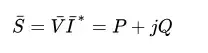
When we look at two buses, each defined by its voltage magnitude and phase angle, and connected by a Transmission Line with a specific impedance, the current flowing between them can be expressed as...
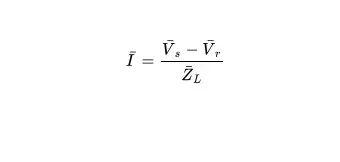
Apparent power flow, along with real and reactive power, is figured out by combining a couple of equations.
This gives us the real and reactive power flow based on voltages and impedance. The process isn’t too complicated and is usually done with load-flow and power analysis software, but the resulting equations can get pretty tricky to interpret.
To make things easier, two common approximations are used: first, we assume a lossless Transmission Line (which is reasonable when using very low resistance conductors), and second, we ignore capacitance on the line (which is usually fine for lines at 200kV and below). This simplification means we only look at the line impedance as reactance, leading to real and reactive power being expressed as...
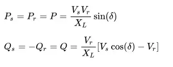
where
- VsV_{s}Vs is the magnitude of the Sending-End Voltage at the first bus,
- VrV_{r}Vr is the magnitude of the Receiving-End Voltage at the second bus,
- XLX_{L}XL is the reactance of the Transmission Line between the buses,
- δ\deltaδ is the phase angle difference between the sending-end and receiving-end voltages.
From these equations, it’s clear that three main variables influence real and reactive power flow on a Transmission Line: the voltage magnitudes at each bus, the line reactance between them, and the phase angle difference between their voltages. All FACTS devices work on the basic idea that changing one or more of these variables will affect the real and reactive power flow on the transmission line. Some devices tweak just one variable, while others manage all three.
It's important to keep in mind, as we’ll discuss later, that FACTS devices don’t generate or add real power to the system. Instead, they change the circuit parameters between two points to influence how and when power flows.
Types of FACTS Devices
Since FACTS devices can modify up to three parameters—voltage, impedance, and/or phase angle—they’re usually classified by the main parameter they control. Traditional devices for voltage (like shunt capacitors and reactors) and impedance control (like series capacitors and load-flow reactors) lead to FACTS devices being grouped into shunt and series devices.
Shunt Compensation Devices
Shunt compensation is all about boosting voltage and allowing for more power flow by connecting a device in parallel with the system. This is typically done using shunt capacitors and inductors (reactors), similar to Power Factor Correction.
The most common shunt compensation device is the Static VAR Compensator (SVC). SVCs use power electronics, usually Thyristors, to switch fixed capacitors and reactors. These setups are called Thyristor Switched Capacitor (TSC) and Thyristor Switched Reactor (TSR), respectively. Thyristors can switch super fast, which gives precise control over reactive power generation by the reactor. When used like this, the TSR is called a Thyristor Controlled Reactor (TCR). TCRs can create a lot of harmonics, so they need Filter Banks to help reduce negative effects on the system.
Another type of shunt compensation is the Static Synchronous Compensator (STATCOM). This device combines power electronics with a reactor to make a Voltage-Sourced Converter (VSC). When this is connected to an AC system, it becomes a STATCOM. VSCs work by measuring the system voltage and adjusting the voltage of the power electronics to control the flow of reactive power into or out of the STATCOM. Early STATCOMs used thyristors for power electronics and Pulse-Width Modulation (PWM) for controlling reactive power, but thanks to advances in semiconductor tech, Insulated-Gate Bipolar Transistors (IGBTs) are now often used instead.
Series Compensation Devices
Series compensation devices change the impedance of the Transmission Line to either boost or reduce power flow. You can increase power flow by adding a series capacitor to balance out line inductance, or decrease it by using a series load-flow reactor to add to the line inductance.
One type of series compensation is the Thyristor-Controlled Series Capacitor (TCSC). This device combines a TCR from an SVC with a regular fixed series capacitor. Because switching capacitors at super-fast intervals can be tricky due to stored charge, a TCR is used to dynamically adjust inductance and offset the capacitor. This setup lets you make quick adjustments to power flow on a transmission line.
A Voltage-Sourced Converter (VSC) can also act as a series compensation device when connected across the secondary winding of a series-connected transformer. This setup is called a Static Synchronous Series Compensator (SSSC). It has benefits like needing a smaller reactor compared to a TCSC and producing fewer harmonics because of the VSC (also known as a Voltage-Source Inverter, or VSI, in this context) compared to a TCR.
Phase Angle Compensation
Power transmission between two points in an AC system only happens when there’s a phase angle difference between the buses. This is usually managed by generators, but in larger grids, it’s less effective for controlling power flow over long distances. In these cases, Phase-Shifting Transformers (PST) are often used as Phase-Angle Regulators (PAR) or to control both phase angle and voltage.
A simple way to handle phase angle compensation is to swap out the tap changer on a PAR with thyristors. This lets you selectively switch parts of the winding in and out, creating a Thyristor-Controlled Phase-Shifting Transformer (TCPST). However, this isn’t usually done because it tends to be more expensive than a regular PAR. Instead, we can expand the idea by replacing a Quadrature Booster with something called a Thyristor-Controlled Phase-Angle Regulator (TCPAR), also known as a Static Phase-Shifter (SPS). A TCPAR pretty much swaps out the mechanical parts of the exciter and booster transformers for power electronics, usually thyristors, as shown in the schematic.
Another way to set up a TCPAR is by separating the exciter and booster transformers and controlling their secondaries with different sets of power electronics. These sets are linked via a DC bus, often using GTO thyristors or IGBTs, to create a TCPAR. While this might seem a bit complex at first, it’s similar to how shunt and series transformers work with their electronics. The shunt part works like a STATCOM, and the series part acts like a Static Synchronous Series Compensator (SSSC). With power flowing from the shunt section through the DC bus to the series section, the device functions as a Phase-Angle Regulator. The DC bus lets the shunt voltage be controlled independently by the STATCOM and the line impedance by the SSSC. This all-in-one capability leads to the Unified Power Flow Controller (UPFC), which can manage all three key parameters that affect power flow control.
Frequently Asked Questions
What is a flexible AC transmission system?
Flexible AC transmission system (FACTS) devices are a group of power electronic-based tools that are becoming more popular in the power system transmission grid. These devices can do a lot of cool things, like boosting power transfer capacity, improving grid stability, and providing quick reactive power and voltage support.
What are the disadvantages of flexible alternating current transmission systems?
There are some downsides to FACTS. For one, there can be considerable losses in the motor. The maintenance costs can be high because of the rotating components. Plus, at lower power ratings, the costs can be pretty steep compared to static capacitors. Also, since synchronous equipment doesn’t start itself, you need extra excitation equipment to get it going.
What is flexible power transmission?
Flexible power transmission includes things like belt drives, chain drives, and rope drives. Because these components are flexible, they’re called flexible drives. They’re usually used for short-distance power transmission, but wire ropes can also work for longer distances.
What is alternating current transmission?
Alternating current (AC) is used to transmit information, like in telephone and cable TV systems. Information signals travel over a wide range of AC frequencies. For example, POTS telephone signals have a frequency of about 3 kHz, which is close to the baseband audio frequency.
Related Articles
Servo Motor vs. Stepper Motor:Which is Best?

Christopher Anderson
Christopher Anderson has a Ph.D. in electrical engineering, focusing on power electronics. He’s been a Senior member of the IEEE Power Electronics Society since 2021. Right now, he works with the KPR Institute of Engineering and Technology in the U.S. He also writes detailed, top-notch articles about power electronics for business-to-business electronics platforms.
Subscribe to JMChip Electronics !