
Murata Electronics GRM31CR60J107ME39L


- Part Number:
GRM31CR60J107ME39L
- Manufacturer:
- Category:
- RoHs:
 RoHS Compliant
 - Datasheet:
 GRM31CR60J107ME39L_Datesheet
 - Description:
CAP CER 100UF 6.3V X5R 1206
- In stock 15,452
Min: 1Mult: 1
Unit Price: $Subtotal: $

GRM31CR60J107ME39L Technical Specifications
Overview
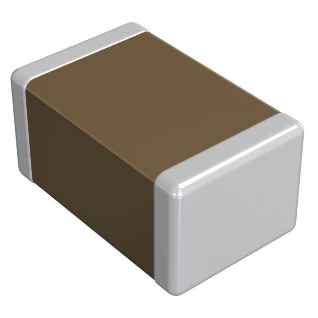
The GRM31CR60J107ME39L is a Chip Monolithic Ceramic Capacitor designed for general electronic equipment. This document outlines its detailed specifications and test methods as of March 3, 2016.
Part Number Breakdown
- GRM: Manufacturer's Prefix (Murata)
- 31C: Size Code (Dimensions)
- R60: Temperature Characteristic (X7R, EIA Standard)
- J107: Capacitance Code (10uF)
- M: Tolerance (±20%)
- E39: Packaging Code
Dimensions
- Length (L): 3.2 mm ± 0.2 mm
- Width (W): 1.6 mm ± 0.1 mm
- Height (T): 0.9 mm ± 0.2 mm
Rated Values
- Capacitance: 10 uF
- Rated Voltage: DC 50V
- Temperature Range: -55°C to +125°C
- Capacitance Tolerance: ±20%
- Temperature Coefficient: X7R (EIA Standard)
Packaging
- Reel Size:180 mm Reel (Embossed Tape, W8P4): 3000 pcs./Reel330 mm Reel (Embossed Tape, W8P4): 10000 pcs./Reel
Specifications and Test Methods
Rated Voltage
- Maximum continuous voltage: DC 50V
- AC voltage superimposed on DC voltage: Ensure VP-P or VO-P does not exceed rated voltage.
Appearance
- No defects or abnormalities. Visual inspection required.
Dimension
- Within specified dimensions. Calipers used for measurement (Microscope for GRM02 size).
Voltage Proof
- No defects or abnormalities.
- Test Voltage: 300% of rated voltage (Temperature compensating type)
- Applied Time: 1 to 5 seconds.
- Charge/Discharge Current: 50mA max.
Insulation Resistance (I.R.)
- For capacitance ≤ 0.047µF: More than 10000MΩ
- For capacitance > 0.047µF: More than 500Ω·F
- Measurement Point: Between terminations.
- Measurement Voltage: DC Rated Voltage.
- Charging Time: 2 minutes.
- Charge/Discharge Current: 50mA max.
- Measurement Temperature: Room Temperature.
Capacitance
- As specified in rated value.
- Measurement Temperature: Room Temperature.
Dissipation Factor (D.F.)
- For capacitance ≥ 30pF: Q ≥ 1000 (W.V.: 100Vdc)
- For capacitance < 30pF: Q ≥ 400 + 20C (W.V.: 100Vdc)
- For capacitance ≥ 30pF: D.F. ≤ 0.025 (W.V.: 100Vdc)
- For capacitance < 30pF: D.F. ≤ 0.05 (W.V.: 100Vdc)
Temperature Characteristics of Capacitance
- Capacitance change measured after 5 minutes at each specified temperature stage.
- Temperature ranges and allowable changes vary by part number:B1, R1, B3, R6, R7: Within ±15% (-55°C to +125°C)C6, C7, C8: Within ±22% (-55°C to +105°C)E7: Within +22/-56% (-55°C to +125°C)D7, D8: Within +22/-33% (-55°C to +105°C)
Adhesive Strength of Termination
- No removal of terminations or other defects.
- Solder the capacitor on the test substrate.
- Holding Time: 10±1 seconds.
- Applied Direction: Parallel with the test substrate and vertical with the capacitor side.
Vibration
- Appearance: No defects or abnormalities.
- Capacitance: Within specified initial value.
- D.F.: Within specified initial value.
- Vibration: Simple harmonic motion (10Hz to 55Hz to 10Hz, total amplitude 1.5mm, applied for 2 hours in each of 3 perpendicular directions, totaling 6 hours).
Substrate Bending Test
- Appearance: No defects or abnormalities.
- Capacitance Change: Within ±5% or ±0.5pF (Whichever is larger).
- Pressurization Method: As shown in Fig.2.
- Flexure: 1mm.
- Holding Time: 5±1 seconds.
- Soldering Method: Reflow soldering.
Solderability
- 95% of the terminations must be soldered evenly and continuously.
- Test Method: Solder bath method.
- Flux Solution: 25% rojin ethanol.
- Preheat: 80°C to 120°C for 10 to 30 seconds.
- Solder: Sn-3.0Ag-0.5Cu.
- Solder Temp: 245±5°C.
- Immersion Time: 2±0.5 seconds.
Resistance to Soldering Heat
- Appearance: No defects or abnormalities.
- Capacitance Change: Within ±2.5% or ±0.25pF (Whichever is larger).
- D.F.: Within specified initial value.
- Exposure Time: 24±2 hours.
- Initial measurement: Perform heat treatment at 150±10°C for 1 hour, then let sit for 24±2 hours at room temperature before measuring.
Temperature Sudden Change
- Appearance: No defects or abnormalities.
- Capacitance Change: Within ±2.5% or ±0.25pF (Whichever is larger).
- D.F.: Within specified initial value.
- I.R.: Within specified initial value.
- Exposure Time: 24±2 hours.
- Initial measurement: Perform heat treatment at 150±10°C for 1 hour, then let sit for 24±2 hours at room temperature before measuring.
High Temperature High Humidity (Steady)
- Appearance: No defects or abnormalities.
- Capacitance Change: Within ±7.5% or ±0.75pF (Whichever is larger).
- D.F.: For capacitance ≥ 30pF: Q ≥ 200 (W.V.: 100Vdc)
- I.R.: More than 500MΩ or 25Ω·F (Whichever is smaller)
- Exposure Time: 24±2 hours.
- Initial measurement: Perform heat treatment at 150±10°C for 1 hour, then let sit for 24±2 hours at room temperature before measuring.
Durability Test
- Appearance: No defects or abnormalities.
- Capacitance Change: Within ±3% or ±0.3pF (Whichever is larger).
- D.F.: For capacitance ≥ 30pF: Q ≥ 350 (W.V.: 100Vdc)
- I.R.: More than 1,000MΩ or 50Ω·F (Whichever is smaller)
- Exposure Time: 24±2 hours.
- Initial measurement: Perform heat treatment at 150±10°C for 1 hour, then let sit for 24±2 hours at room temperature before measuring.
Storage and Operation Conditions
- Store capacitors at room temperature (+5°C to +40°C) and relative humidity (20% to 70%).
- Avoid sunlight, dust, rapid temperature changes, corrosive gases, and high humidity.
- Use within six months to prevent oxidation of terminations.
- Confirm solderability before using after six months.
- Do not store in an atmosphere containing corrosive gases (e.g., hydrogen sulfide, sulfur dioxide, chlorine, ammonia).
Caution
- Applications: Contact Murata before using in applications requiring high reliability (e.g., aircraft, aerospace, medical equipment).
- Voltage: Do not exceed rated voltage. Consider AC voltage, pulse voltage, and surge voltage.
- Temperature Dependency: Capacitance may change with temperature. Select appropriate capacitance for operating temperature range.
- Measurement: Measure capacitance with specified voltage and frequency.
- Soldering: Follow recommended soldering conditions to prevent mechanical damage.
- Mounting: Choose mounting position to minimize stress during PCB flexing or bending.
Conclusion
The GRM31CR60J107ME39L is a reliable ceramic capacitor suitable for a wide range of electronic applications. Its detailed specifications and test methods ensure high performance and reliability. For further information or specific application requirements, please consult Murata's approval sheet or contact their technical support.
Purchase
No need to register to order from JMChip Electronics, but signing in lets you track your order like a pro. Give it a try for a smoother shopping ride.
Means
Easy peasy! Pay your way with PayPal, Credit Card, or wire transfer in USD. We've got you covered.
RFQ(Request for Quotations)
Get the freshest prices and stock updates by asking for a quote! Our sales team will shoot you an email within a day. It's that simple.
IMPORTANT NOTICE
1. Look out for your order details in your inbox! (If it's missing, check the spam folder just in case.)
2. Our sales manager will double-check the order and keep you posted on any price or stock changes. No worries, we've got you covered.

Shipping Rate
We ship orders once a day around 5 p.m., except Sunday. Once shipped, the estimated delivery time depends on the courier company you choose, usually 5-7 working days.

Shipping Methods
We provide DHL, FedEx, UPS, EMS, SF Express, and Registered Air Mail international shipping.


Payment
You can pay the orders on the website directly or pay by wire transfer offline. We support: Paypal、VISA、Credit Card.


Murata Electronics
Murata Electronics
Murata Electronics
Murata Electronics
Murata Electronics
Murata Electronics
Murata Electronics
Murata Electronics
Murata Electronics
Murata Electronics
Murata Electronics
Murata Electronics