
Analog Devices Inc.(ADI) MAX1736EUT41+


- Part Number:
MAX1736EUT41+
- Manufacturer:
- Category:
- RoHs:
 RoHS Compliant
 - Datasheet:
- Description:
INTEGRATED CIRCUIT
- In stock 0

MAX1736EUT41+ Datasheet Comprehensive Summary
1. Overview
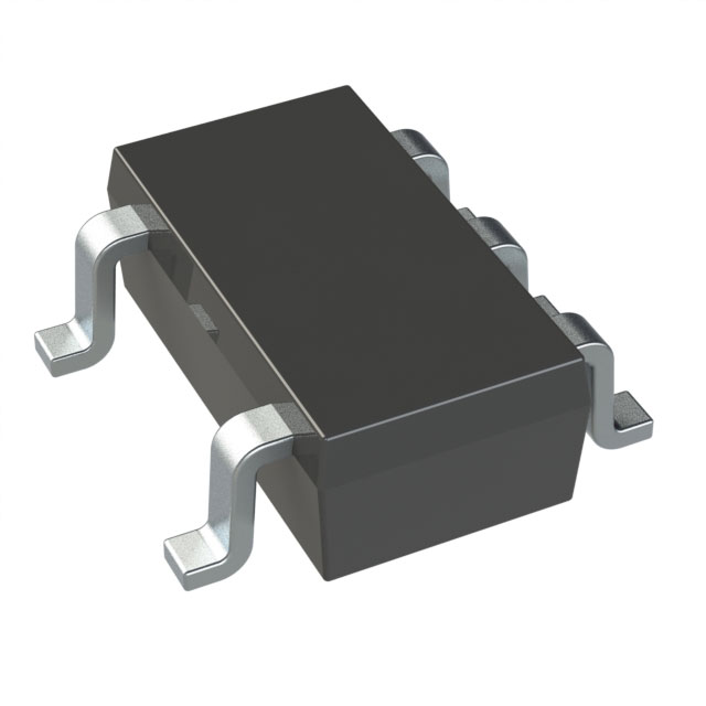
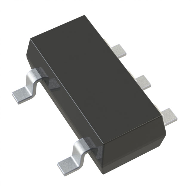
The MAX1736EUT41+ is a compact, low-cost single-cell lithium-ion (Li⁺) battery charger from Maxim Integrated, optimized for small hand-held devices. It works with a current-limited voltage source (e.g., wall cube adapters) to provide safe, accurate charging—including precharge, fast charge, and pulsed top-off modes—while minimizing power dissipation. This variant is preset to a 4.1V battery regulation voltage (critical for Li⁺ cell safety) and packaged in a tiny 6-pin SOT23, making it ideal for space-constrained applications like wireless handsets, digital cameras, and personal digital assistants (PDAs).
2. Key Features
2.1 Core Functional Capabilities
- Charging Modes: Three-stage charging (precharge → fast charge → pulsed top-off) to ensure safe, full-capacity charging:
- Voltage Regulation: Preset 4.1V regulation voltage with 0.5% set-point accuracy (critical for Li⁺ cell longevity; overcharging causes permanent damage).
- Control Flexibility: Stand-alone operation (no microprocessor required) or µP-controlled via the EN pin; automatic shutdown when input power is removed to minimize battery drain.
2.2 Electrical & Environmental Specifications
- Input Voltage: 4.7V (minimum, PFET off) to 22V (maximum), compatible with most wall cubes and adapters.
- Power Efficiency: Low power dissipation (no inductor required) and minimal quiescent current:
- Temperature Range:
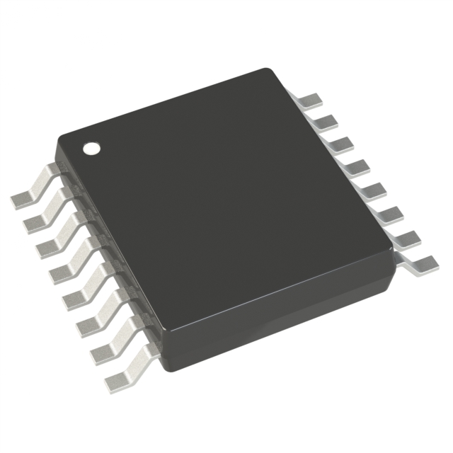
- Package: 6-pin SOT23 (small outline transistor), dimensions: 2.80–3.00mm (length) × 2.60–3.00mm (width) × 0.90–1.45mm (height).
3. Pin Configuration & Function
The MAX1736EUT41+ features 6 pins with dedicated roles for power, control, and charging. Pin details are summarized below (top-view orientation):
| Pin # | Pin Name | I/O Type | Core Function | Key Notes |
|---|---|---|---|---|
| 1 | IN | Input | Input voltage from current-limited supply | Bypass to GND with a 0.1µF capacitor; max voltage = 22V. When PFET is on, IN ≈ VBATT (may drop to 2.5V). |
| 2 | GATE | Output | Gate drive for external PFET | Drives the PFET’s gate to turn it on/off; requires external components (RGATE, CGATE) to slow switching and prevent transients. |
| 3 | GND | -- | Ground | Connect to the battery’s negative terminal; use large copper traces for low-impedance grounding. |
| 4 | EN | Input | Enable/disable control | Logic low (≤ 0.7V) = disable charger; logic high (≥ 2V) = enable. Internally pulled up to VBATT + 100mV via 350kΩ (no current draw from BATT). |
| 5 | CT | Input | Charge time control | Connect a capacitor (typically 0.33µF) to GND to set minimum on/off times and input detection interval. |
| 6 | BATT | I/O | Battery connection & power source | Connect to the Li⁺ cell’s positive terminal; bypass with ≥1.5µF capacitor per amp of charge current (low-ESR ceramic recommended). Also serves as the MAX1736’s power source. |
4. Electrical Specifications (TA = -40°C to +85°C, VIN = 10V, VBATT = 4.1V)
4.1 Critical Charging Parameters
| Parameter | Conditions | Min | Typ | Max | Unit |
|---|---|---|---|---|---|
| Battery Regulation Voltage | MAX1736EUT41+ | 4.058 | 4.10 | 4.142 | V |
| Precharge Current | VBATT = 2V | 3 | 6 | 8 | mA |
| Fast-Charge Qualification Threshold | VBATT rising (precharge → fast charge) | 2.4 | 2.5 | 2.65 | V |
| Fast-Charge Threshold Hysteresis | -- | -- | 70 | -- | mV |
| Battery Removal Detection Threshold | VBATT rising | 4.85 | 5.0 | 5.125 | V |
| Battery Removal Hysteresis | -- | -- | 125 | -- | mV |
4.2 Control & Power Parameters
| Parameter | Conditions | Min | Typ | Max | Unit |
|---|---|---|---|---|---|
| EN Logic High Threshold | -- | 2 | -- | -- | V |
| EN Logic Low Threshold | -- | -- | -- | 0.7 | V |
| EN Pullup Resistance | -- | 170 | 350 | 725 | kΩ |
| IN Input Current | -- | -- | 0.25 | 1 | mA |
| Battery Current (Input Power Removed) | VIN ≤ VBATT - 0.3V | -- | 0.1 | 1 | µA |
| GATE Source/Sink Current | -- | 60 | 100 | 140 | µA |
4.3 CT Capacitor-Dependent Parameters (CCT = 0.33µF)
| Parameter | Value (Typ) | Unit |
|---|---|---|
| Minimum On-Time (tON(MIN)) | 165 | ms |
| Minimum Off-Time (tOFF(MIN)) | 33 | ms |
| Input Detection Interval | 20 | s |
5. Recommended External Components
The MAX1736EUT41+ requires minimal external components for operation. Key selections are:
| Component | Type | Value | Purpose |
|---|---|---|---|
| PFET (Pass Element) | P-channel MOSFET | e.g., FDC638P | Switches the current-limited supply to the battery; requires VGS(th) ≤ 2.5V and BVDS ≥ 2× wall cube voltage. |
| RGATE | Resistor | 100kΩ | Slows PFET gate slew rate to prevent transient spikes. |
| CGATE | Capacitor | 0.22µF | Further dampens PFET switching transients (increase for poor-quality wall cubes). |
| CCT | Capacitor | 0.33µF | Sets minimum on/off times and input detection interval (equation: tON(MIN) = 5×10⁵ × CCT; tOFF(MIN) = 1×10⁵ × CCT). |
| BATT Bypass Capacitor | Low-ESR ceramic | ≥1.5µF/A (charge current) | Stabilizes VBATT and prevents voltage transients; max 100µF (to avoid excessive current when replacing batteries). |
| IN Bypass Capacitor | Ceramic | 0.1µF | Filters noise from the input supply. |
6. Charging Operation & State Machine
The MAX1736EUT41+ follows a safety-focused state machine to charge Li⁺ cells, as outlined below:
6.1 1. Precharge Mode
- Trigger: VBATT < 2.5V (e.g., near-dead battery).
- Action: The MAX1736EUT41+ activates an internal 6mA current source to slowly charge the cell, preventing damage from high currents.
- Exit Condition: VBATT rises above 2.5V (plus 70mV hysteresis to avoid oscillation).
6.2 2. Fast Charge Mode
- Trigger: VBATT ≥ 2.5V and input power is present.
- Action: Turns on the external PFET, connecting the current-limited supply directly to the battery. Charging current is set by the supply’s current limit (not the MAX1736).
- Monitoring: Periodically turns off the PFET every 20s (CCT = 0.33µF) to check if input power is present; shuts down if power is removed.
- Exit Condition: VBATT reaches the 4.1V regulation voltage.
6.3 3. Pulsed Top-Off Mode
- Trigger: VBATT ≥ 4.1V (fast charge complete).
- Action: Uses hysteretic PWM to maintain safe charging:
- Exit Condition: VBATT no longer drops below 4.1V between pulses (battery fully charged).
6.4 Shutdown Modes
- Input Power Removed: Detected during periodic IN checks; shuts down to minimize battery drain (current ≤ 1µA).
- EN Pin Disabled: EN = GND; turns off the PFET and disables charging (current ≤ 6µA).
- Battery Removal: Detects VBATT > 5.125V (transient when battery is disconnected); immediately turns off the PFET.
7. Layout Guidelines
To ensure reliable performance and minimize noise:
- Grounding: Use a large ground plane and wide traces for high-current paths (IN → PFET → BATT → GND) to reduce impedance and heat.
- Component Placement:
- Trace Sizing: Use traces rated for the supply’s current limit (e.g., 0.5mm width for 1A current).
- Thermal Management: The SOT23 package dissipates minimal heat, but avoid placing heat-generating components (e.g., voltage regulators) nearby.
8. Ordering Information & Part Details
| Part Number | Temperature Range | Package | SOT Mark | Key Notes |
|---|---|---|---|---|
| MAX1736EUT41-T | -40°C to +85°C | 6-pin SOT23-6 | AANC | Tape-and-reel packaging; preset to 4.1V regulation. |
8.1 Soldering Requirements
- Solder Profile: Must follow IPC/JEDEC J-STD-020A (IR/VPR or convection reflow); preheating is mandatory.
- Lead Temperature: Max 300°C for 10 seconds (hand/wave soldering is not allowed).
- Thermal Derating: 6-pin SOT23 dissipates 0.65W at TA = 70°C; derate 8.1mW/°C above 70°C.
9. Typical Applications
The MAX1736EUT41+ is ideal for single-cell Li⁺ battery-powered devices, including:
- Wireless handsets and smartphones.
- Personal Digital Assistants (PDAs) and portable media players.
- Digital cameras and camcorders.
- Small hand-held equipment (e.g., Bluetooth headsets, portable scanners).
- Self-charging battery packs and cradle chargers.
10. Key Safety & Reliability Notes
- Li⁺ Cell Compatibility: Designed exclusively for single-cell Li⁺ batteries (3.6V nominal); do not use with other chemistries (e.g., NiCd, NiMH).
- Overcharge Protection: The 4.1V regulation voltage prevents overcharging (critical for Li⁺ cell safety—overcharging causes thermal runaway).
- ESD Protection: Internal ESD protection, but handle components with anti-static measures.
- Quality Assurance: 100% tested at TA = +25°C; limits over the operating temperature range are guaranteed by design.
Purchase
No need to register to order from JMChip Electronics, but signing in lets you track your order like a pro. Give it a try for a smoother shopping ride.
Means
Easy peasy! Pay your way with PayPal, Credit Card, or wire transfer in USD. We've got you covered.
RFQ(Request for Quotations)
Get the freshest prices and stock updates by asking for a quote! Our sales team will shoot you an email within a day. It's that simple.
IMPORTANT NOTICE
1. Look out for your order details in your inbox! (If it's missing, check the spam folder just in case.)
2. Our sales manager will double-check the order and keep you posted on any price or stock changes. No worries, we've got you covered.

Shipping Rate
We ship orders once a day around 5 p.m., except Sunday. Once shipped, the estimated delivery time depends on the courier company you choose, usually 5-7 working days.

Shipping Methods
We provide DHL, FedEx, UPS, EMS, SF Express, and Registered Air Mail international shipping.


Payment
You can pay the orders on the website directly or pay by wire transfer offline. We support: Paypal、VISA、Credit Card.


Analog Devices Inc.(ADI)
Analog Devices Inc.(ADI)
Analog Devices Inc.(ADI)
Analog Devices Inc.(ADI)
Analog Devices Inc.(ADI)
Analog Devices Inc.(ADI)
Analog Devices Inc.(ADI)
Analog Devices Inc.(ADI)
Analog Devices Inc.(ADI)
Analog Devices Inc.(ADI)
Analog Devices Inc.(ADI)
Analog Devices Inc.(ADI)