Categories
  • PFC (Power Factor Correction)(31)
View Mode:result_1_0result_1_1result_2_0result_2_1
Email

Leave Us A Message!

We`re not around but we still want to hear from you! Leave us a note:

SEND
EmailWhatsApp
*You can contact us directly on WhatsApp!
  • img

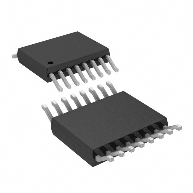
    LT8312MPMS#TRPBF

    IC PFC CTRLR DCM 400KHZ 16MSOP

    Analog Devices Inc.(ADI)

  • img

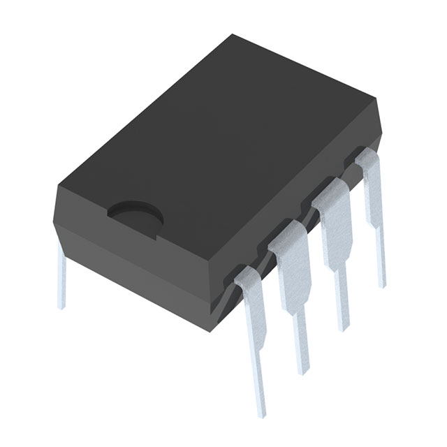
    LT1249IN8#PBF

    IC PFC CTR AVER CURR 100KHZ 8DIP

    Analog Devices Inc.(ADI)

  • img

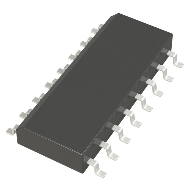
    LT1248IS#TRPBF

    IC PFC CTR AVERAGE 300KHZ 16SOIC

    Analog Devices Inc.(ADI)

  • img

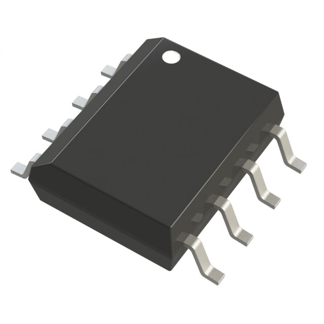
    LT1249IS8#TRPBF

    IC PFC CTR AV CURR 100KHZ 8SOIC

    Analog Devices Inc.(ADI)

  • img

    LT1509ISW#TRPBF

    IC PFC CTR AVERAGE 100KHZ 20SOIC

    Analog Devices Inc.(ADI)

  • img

    LT1509CSW#TRPBF

    IC PFC CTR AVERAGE 100KHZ 20SOIC

    Analog Devices Inc.(ADI)

  • img

    LT1249CS8#TRPBF

    IC PFC CTR AV CURR 100KHZ 8SOIC

    Analog Devices Inc.(ADI)

  • img

    LT1508IN

    IC PFC CTR AV CURR 100KHZ 20DIP

    Analog Devices Inc.(ADI)

  • img

    LT1508CN

    IC PFC CTR AV CURR 100KHZ 20DIP

    Analog Devices Inc.(ADI)

  • img

    LT8312HMS#TRPBF

    IC PFC CTRLR DCM 400KHZ 16MSOP

    Analog Devices Inc.(ADI)

  • img

    LT8312IMS#TRPBF

    IC PFC CTRLR DCM 400KHZ 16MSOP

    Analog Devices Inc.(ADI)

  • img

    LT8312EMS#TRPBF

    IC PFC CTRLR DCM 400KHZ 16MSOP

    Analog Devices Inc.(ADI)

  • img

    LT8312MPMS#PBF

    IC PFC CTRLR DCM 400KHZ 16MSOP

    Analog Devices Inc.(ADI)

  • img

    LT1248IN#PBF

    IC PFC CTR AV CURR 300KHZ 16DIP

    Analog Devices Inc.(ADI)

  • img

    LT1509CN#PBF

    IC PFC CTR AV CURR 100KHZ 20DIP

    Analog Devices Inc.(ADI)

  • img

    LT1509IN#PBF

    IC PFC CTR AV CURR 100KHZ 20DIP

    Analog Devices Inc.(ADI)

  • img

    ADP1048WARQZ-R7

    IC PFC CTR AVERAGE 400KHZ 24QSOP

    Analog Devices Inc.(ADI)

  • img

    LT1248CS#TRPBF

    IC PFC CTR AVERAGE 300KHZ 16SOIC

    Analog Devices Inc.(ADI)

  • img

    ADP1047ARQZ-R7

    IC PFC CTR AVERAGE 400KHZ 24QSOP

    Analog Devices Inc.(ADI)

  • img

    LT8312IMS#PBF

    IC PFC CTRLR DCM 400KHZ 16MSOP

    Analog Devices Inc.(ADI)

  • Total 31
    • 1
    • 2

    Description of PFC (Power Factor Correction)

    Power Factor Correction (PFC) is a semiconductor device designed to align the phase angle to approach zero between the voltage and current in an AC circuit. The different modes are average current, boundary conduction, continuous conduction, critical conduction, current controlled frequency foldback, discontinuous, and discontinuous conduction with a frequency switching of adjustable and 6kHz to 1.7MHz.
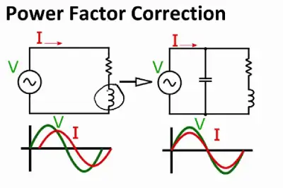
    PFC (Power Factor Correction)

    What is Power Factor Correction?

    Power factor correction is a way to improve the power factor of a power supply. Without it, switching power supplies pull current in short, high-magnitude bursts. These bursts can be smoothed out using active or passive methods, which helps reduce the input RMS current and apparent input power, thereby boosting the power factor.

    Power factor correction shapes the input current to get the most real power from the AC supply. Ideally, electrical equipment should act like a pure resistor, meaning no reactive power and current and voltage waveforms would be perfectly in sync. But, most circuits have reactive components that cause a power lag, which lowers the power factor.

    In a perfect system, all the power from the AC mains would be used effectively for useful work, but that only happens when the current and voltage are in phase. If they’re out of sync, some of the energy from the AC outlet isn’t used effectively and gets wasted.

    Advantages and Disadvantages of an Active PFC

    Advantages of an Active PFC

    • Achieves a power factor of 0.95 or higher
    • Small and lightweight
    • Handles a wide range of AC input voltages and frequencies (87 Vrms - 266 Vrms and 47Hz - 63Hz)
    • More flexible
    • Offers greater control

    Disadvantages of an Active PFC

    • More complex
    • Higher cost
    • Needs extra filtering to handle high frequencies that might interfere with the line
    • Components need to be rated for higher voltages compared to passive PFCs

    Benefits of PFC

    When the power factor is as close to 1 as possible, it means lower losses and all the power generated is used more efficiently.

    Technical Benefits:

    • Improved efficiency
    • Lower power demand, which means less strain on switching gear and cables
    • Reduced costs for consumers
    • Ability to support more load

    Commercial Benefits:

    • Lower system losses
    • Reduced capital costs for the generating company
    • Savings on electricity bills because there are no extra charges for reactive power
    • Transmission and distribution equipment runs cooler and lasts longer

    Environmental Benefits:

    • Lower CO2 emissions
    Filters
    ApplyReset All
    • Manufacturers
    • Stocking Options
    • Environmental Options
    • Current - Startup
    • Frequency - Switching
    • Grade
    • Mode
    • Mounting Type
    • Operating Temperature
    • Package / Case
    • Qualification
    • Supplier Device Package
    • Voltage - Supply
    Attribute column