
Categories
- RF Directional Coupler(1)


- 1
Introduction of RF Directional Coupler
1. Directional Couplers
- Basic Function: Sample isolated (reverse) signals, commonly used for measuring reflected power (or indirectly, VSWR).
- Advantages:Can be optimized for the forward path.High directivity and isolation.Isolation ports are internally terminated for optimal performance.
- Disadvantages:Coupling can only be done on the forward path.No coupling line.The power rating of the coupling port is less than the input port because the power applied to the coupling port is almost entirely dissipated in the internal termination.
- Example: Mini-Circuits ZCDC20-E18653+ is a coaxial directional coupler with a frequency range of 18 to 65 GHz, providing a nominal coupling value of 20 dB, capable of handling up to 12W of RF input power.
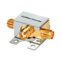
2. Bi-directional Couplers
- Basic Function: Feature four ports to sample both forward and reverse signals simultaneously.
- Advantages:Symmetric design.Input and output ports can be interchanged.Two transmission lines, with coupling lines identical to the main line.Provide both forward and reverse coupling.
- Disadvantages:Design is critical to maintaining good performance in both directions.The directivity of the coupler depends on the termination of the isolation port.
- Example: Mini-Circuits ZGBDC35-93HP+ is a coaxial bi-directional coupler with a frequency range of 900 MHz to 9 GHz, providing a nominal coupling value of 35 dB, capable of handling up to 250W of RF input power.
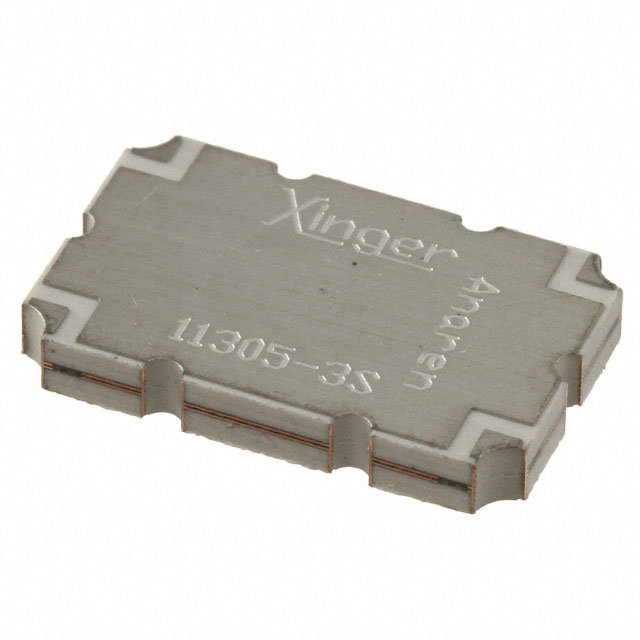
3. Dual Directional Couplers
- Basic Function: Two 3-port couplers combined in series with the main line, with internal termination ports relative between the couplers.
- Advantages:Can be optimized for both forward and reverse paths.Higher directivity and isolation.Provide both forward and reverse coupling.The directivity of one path is not affected by mismatches on the other path.Can monitor both forward and reverse power of the system simultaneously.
- Disadvantages:Typically involves two back-to-back directional couplers.Larger in size compared to directional and bi-directional couplers.No coupling line (not available at either end).Higher insertion loss than individual directional and bi-directional couplers.
- Example: Mini-Circuits DDCH-50-13+ is a surface-mount dual directional coupler based on stripline, with a frequency range of 20 to 1000 MHz, providing a nominal coupling ratio of 50 dB, capable of handling up to 120W of RF input power.
FAQ
Q: What are the main parameters of an RF directional coupler?
A: The main parameters include Coupling, Directivity, Isolation, and Insertion Loss, all of which are expressed in dB.
Q: How do directional couplers work?
A: Directional couplers work by sampling isolated signals to measure reflected power or VSWR. They can be connected in the forward or reverse direction, but they are not reciprocal.
Q: What are the applications of directional couplers?
A: Applications of directional couplers include reflectometers, forward sampling, amplitude balancing of signal generators, and intermodulation test setups for receivers.
Q: What is the difference between bi-directional couplers and dual-directional couplers?
A: Bi-directional couplers can sample both forward and reverse signals simultaneously, while dual directional couplers combine two 3-port couplers to provide independent use of coupling ports and the directivity of one path is not affected by mismatches on the other path.


