
Categories
- PFC (Power Factor Correction)(270)


- 1
- 2
- 3
- 4
- 5
- 6
- 14
Description of PFC (Power Factor Correction)
Power Factor Correction (PFC) is a semiconductor device designed to align the phase angle to approach zero between the voltage and current in an AC circuit. The different modes are average current, boundary conduction, continuous conduction, critical conduction, current controlled frequency foldback, discontinuous, and discontinuous conduction with a frequency switching of adjustable and 6kHz to 1.7MHz.
What is Power Factor Correction?
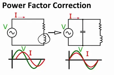
Power factor correction is a way to improve the power factor of a power supply. Without it, switching power supplies pull current in short, high-magnitude bursts. These bursts can be smoothed out using active or passive methods, which helps reduce the input RMS current and apparent input power, thereby boosting the power factor.
Power factor correction shapes the input current to get the most real power from the AC supply. Ideally, electrical equipment should act like a pure resistor, meaning no reactive power and current and voltage waveforms would be perfectly in sync. But, most circuits have reactive components that cause a power lag, which lowers the power factor.
In a perfect system, all the power from the AC mains would be used effectively for useful work, but that only happens when the current and voltage are in phase. If they’re out of sync, some of the energy from the AC outlet isn’t used effectively and gets wasted.
Advantages and Disadvantages of an Active PFC
Advantages of an Active PFC
- Achieves a power factor of 0.95 or higher
- Small and lightweight
- Handles a wide range of AC input voltages and frequencies (87 Vrms - 266 Vrms and 47Hz - 63Hz)
- More flexible
- Offers greater control
Disadvantages of an Active PFC
- More complex
- Higher cost
- Needs extra filtering to handle high frequencies that might interfere with the line
- Components need to be rated for higher voltages compared to passive PFCs
Benefits of PFC
When the power factor is as close to 1 as possible, it means lower losses and all the power generated is used more efficiently.
Technical Benefits:
- Improved efficiency
- Lower power demand, which means less strain on switching gear and cables
- Reduced costs for consumers
- Ability to support more load
Commercial Benefits:
- Lower system losses
- Reduced capital costs for the generating company
- Savings on electricity bills because there are no extra charges for reactive power
- Transmission and distribution equipment runs cooler and lasts longer
Environmental Benefits:
- Lower CO2 emissions


