
Categories
- SCRs - Modules(2,471)


- 1
- 2
- 3
- 4
- 5
- 6
- 124
What is a Silicon Controlled Rectifier (SCR) module?
Products in the SCR module family consist of two or more SCR devices housed within a single package, or a single SCR combined with other components, such as a rectifier diode. Typically used for controlling AC utility power, SCRs (also known as thyristors) function like standard rectifier diodes but have the added capability of blocking current flow in the forward direction until a control pulse is applied.
What are SCRs?
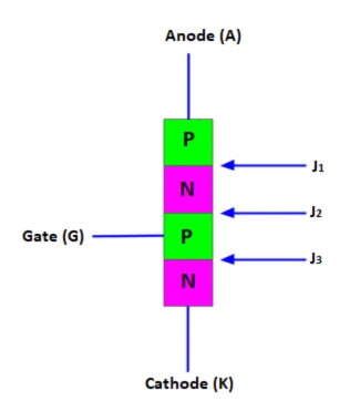
Silicon Controlled Rectifiers (SCRs) are a unidirectional current control device. Similar to a standard p-n junction diode, it permits electric current to flow in one direction while blocking it in the opposite direction. A typical p-n junction diode consists of two layers of semiconductor materials—P-type and N-type. In contrast, an SCR is constructed from four layers of semiconductor materials that alternate between P-type and N-type.
The p-n-p-n switching principle was established in 1956 by Tanenbaum, Goldey, Moll, and Holonyak at Bell Laboratories. The Silicon Controlled Rectifier (SCR) was created by a team of power engineers led by Gordon Hall and was commercialized in 1957 by Frank W. "Bill" Gutzwiller. Initially, this device was commonly referred to as SCR or controlled rectifier, but today it is more widely known as a thyristor.
Silicon Controlled Rectifiers are utilized in power control applications, including managing power to electric motors, relay controls, and induction heating elements, where regulating the power delivered is essential.
SCR Applications
SCRs are employed in various applications, ranging from converter circuits to control circuits. While it's impractical to cover all thyristor applications, their primary function is to manage the current or voltage across a device. For instance, one common application is using SCRs to regulate the speed of a motor.
SCRs circuit diagram
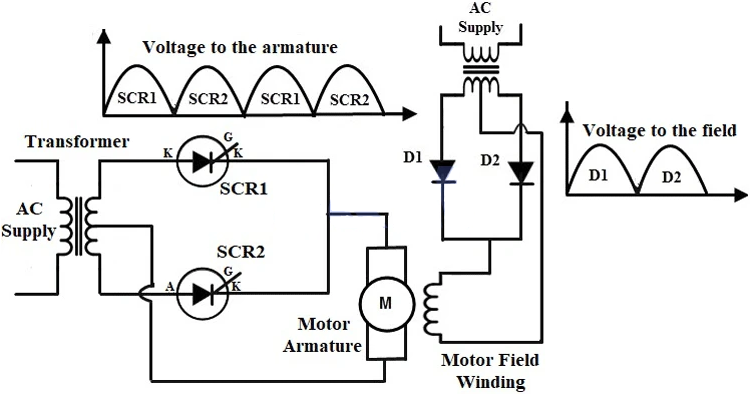
The circuit diagram above illustrates how SCRs are used to control the speed of a DC motor. The motor features two windings: the field winding and the armature winding. By regulating the current supplied to the armature winding, we can adjust the motor's speed. The armature winding connects to an AC supply via a transformer and two SCRs arranged in parallel.
During the positive half-cycle of the AC supply, SCR1 becomes forward-biased and conducts when a gate pulse is applied, allowing current to flow through it to the armature winding. Conversely, in the negative half-cycle, SCR2 is forward-biased while SCR1 is reverse-biased, turning SCR1 off. When a gate pulse is applied to SCR2, it begins conducting. By varying the trigger pulses sent to the gates of each SCR, we can control the input to the DC motor, effectively adjusting its speed.


